Ring binder mechanism

a technology of ring binder and ring head, which is applied in the direction of sheet binding, printing, filing appliances, etc., can solve the problem of achieving defined pretension

Active Publication Date: 2006-10-12
HORN HANS JOHANN
View PDF49 Cites 63 Cited by
  • Summary
  • Abstract
  • Description
  • Claims
  • Application Information

AI Technical Summary

Benefits of technology

[0009] Beginning therewith, it is the task of the present invention to improve the known ring binder mechanisms of the above-described type in such a manner that tolerance problems during the closing process are avoided.

Problems solved by technology

By the relocation of the locking force receiving bearing, away from the housing wall, towards the area of the carrier rails and / or the housing flanks, tolerance problems, which always occur in the manufacturing of the components, are constructively limited to be so small, that even in the case of use of a locking rod with multiple rigidly provided locking elements, a defined pretension can be achieved on all rings of the ring binder mechanism.

Method used


Image

  • Ring binder mechanism
  • Ring binder mechanism
  • Ring binder mechanism

Examples


Embodiment Construction

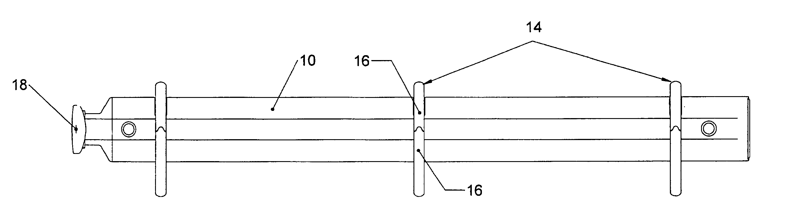
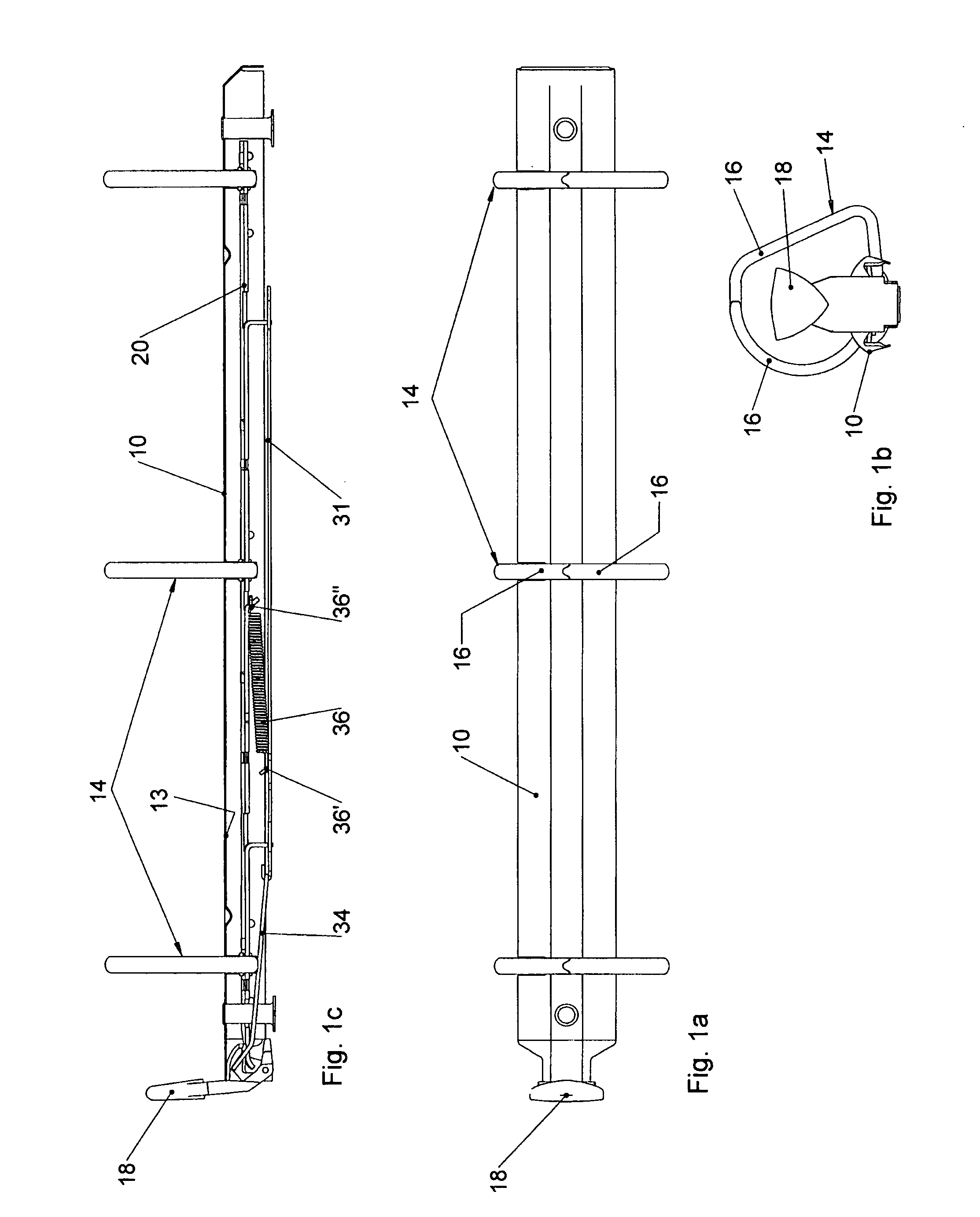
[0065] The ring binder mechanism shown in the figures is intended above all for receiving loose hole-punched sheets, for example stationary or printed materials. The ring binder mechanism is comprised essentially of a housing 10, at least two half-rings 16 provided in defined spacing from each other, extending through openings 12 in a housing wall 13 and pair-wise cooperating to form a ring 14, as well as an actuating element 18 in the form of an actuating lever for opening and closing the rings 14. The half-rings 16 are rigidly secured to two carrier rails 20, which lie against each other along inner longitudinal edges 23 to define a linkage axis 22 and with their outer longitudinal edges 24 engaging in bearing channels 26, stamped into the housing flanks 28. The carrier rails 20 are so introduced into the housing 10, such that they can assume two rest positions, an open and a closed position (see, for example, FIGS. 12a and 12b). The housing 10 functions as a spring element, which...


PUM


Abstract

The invention relates to a ring binder mechanism comprising a housing (10) for receiving two carrier rails (20), wherein the carrier rails are positioned adjacent one another with at least a portion of their inner longitudinal edges (23) facing each other to form a linkage axis (22) and at least a portion of their outer longitudinal edges (24) engaging the housing (10). The carrier rails (20) have at least two half-rings (16) rigidly connected with the carrier rails, which together form a ring (14). The carrier rails (20) are limitedly pivotable relative to each other about the linkage axis (22), taking along the half-rings (16), between an open position and a closed position. A locking rod (31) having at least one locking element (32) is movable parallel to the linkage axis (22) relative to the housing (10) and the carrier rails (20) via an actuating element (18). The locking rod is provided adjacent the bottom or exterior surface of the carrier rails (i.e. the surface facing away from the housing). The locking element (32) engages a portion of the carrier rails and blocks the pivot path of the carrier rails (20) in the closed position. Abutments or bearings are provided on the carrier rails (20) or on the housing flanks (28) for receiving locking forces, against which the locking element (32) is supported in the closed position.

Description

CROSS-REFERENCE TO RELATED APPLICATIONS [0001] This application is based on German Serial No. 10 2006 004 113.5 filed on Jan. 27, 2006, which claims priority to German Serial No. 10 2005 016 900.7 filed on Apr. 12, 2005, both of which are hereby incorporated by reference and to which priority is claimed. STATEMENT REGARDING FEDERALLY SPONSORED RESEARCH OR DEVELOPMENT [0002] Not applicable. BACKGROUND OF THE INVENTION [0003] 1. Field of the Invention [0004] The invention concerns a ring binder mechanism with a housing having a C or U-shaped cross section with spring elastic spreadable flanks for two carrier rails, which on their longitudinal edges facing each other (inward facing) lie against each other to form a linkage or articulation axis and with their longitudinal edges facing away from each other (outward facing) engage in bearing grooves of the housing flanks, and with at least two half-rings rigidly connected with the carrier rails in a defined longitudinal spacing, preferabl...

Claims


Application Information

Patent Timeline
Patent Type & Authority Applications(United States)
IPC IPC(8): B42F13/20
CPCB42F13/26
Inventor HORN, HANS JOHANN
Owner HORN HANS JOHANN
Why Eureka
Try Eureka