
Data storage device with hard drive and interchangeable data storage disks

a data storage device and data storage technology, applied in the field of computer storage devices, can solve the problems of limitation of the prior art, the use of hard drives has not been a cost effective solution the use of hard drives has not been cost effective for large off-line data storage facilities, etc., to achieve cost-effective effects

Inactive Publication Date: 2007-08-30
BAUCK RANDALL CLEMENT +1
View PDF5 Cites 9 Cited by
  • Summary
  • Abstract
  • Description
  • Claims
  • Application Information

AI Technical Summary

Benefits of technology

[0009] In view of the limitations of the prior art, use of hard drives has not been a cost effective solution for large off-line data storage facilities (e.g., archival storage of data) such as data silos and / or for many data back-up applications. Accordingly, it has been recognized that the ability to use multiple data storage disks with a single set of read-write heads could alleviate many of the limitations of the prior art and allow for hard drive storage devices to be utilized for large scale data storage as well as data back-up applications. In such an arrangement, a number of data storage disks may be stored in an inactive state at a storage location and selectively retrieved in an automated process for accessing data therefrom and / or writing data thereto. In addition, one or more selected data storage disks may be securely engaged with a drive hub associated with a set of read-write heads. That is, a single drive hub and a set of read-write heads may be utilized with a plurality of individual data storage disks that are selectively engageable with the drive hub. Such an arrangement eliminates the need of individual read-write heads for individual disks and overcomes previous tolerance problems that typically restricted storage devices to use of no more than about three disks fixedly mounted to a common spindle.
[0011] In order to securely engage a selected data storage disk with the drive hub, the drive hub may include one or more restraining elements that are operative to selectively engage the data storage disk, for example, proximate to the central aperture of the data storage disk. In one arrangement, the restraining elements may be disposed on and / or around a portion of the hub that is disposable through the central aperture of the selected data storage disk. Accordingly, such restraining elements may be moved from an initial position, or open position, to a subsequent, or clamped, position. In such a clamped position, the restraining elements may physically engage a surface of the data storage disk. Further, in the clamped position, the outside dimension, or diameter, of the restraining elements may be greater than the diameter of the central aperture of the data storage disk. Accordingly, in such a position the storage disk may be restrained on the drive hub. Further, the restraining elements may apply a compressive force to a surface of the storage disk and / or apply an outward force (e.g., relative to the drive axis) to the central aperture of the storage disk. Such an outward force may assist in properly centering the storage disk on the drive hub.
[0015] In an arrangement utilizing two or more disk access devices, these disk access devices may be utilized simultaneously and / or redundantly. Further, the multiple access devices may be synchronized by a controller to run in tandem. In this regard, data storage / retrieval may be performed in, for example, a RAID configuration such that high data transfer / retrieval rates are possible.
[0017] In order to remove the storage disks from the storage location, the storage structure may utilize individual actuators that are operative to move the storage disks. Alternatively, the storage structure may utilize gravity to load selected data storage disks into the carriage. For instance, a U-shaped member may be inverted and upright such that disks are inserted into grooves within the concave surface of the structure and are maintained within the grooves by a stop member. When the stop member is removed from the groove, the data storage disk may be operative to drop into the carriage for transport to the disk access device. One or more movable elements / actuators may be utilized to control the drop of the data storage disks to prevent damage thereof.
[0025] According to another aspect, a method is provided wherein a data storage disk may be selectively engaged with a rotating hub of a data access device. The method includes disposing a central aperture of a data storage disk over a centering stud of a drive hub. Once so disposed, a restraining element that is movably connected with the centering stud may be moved from a first position that is within an area defined by the boundary of the central aperture to a second position that is outside the boundary defined by the central aperture. Accordingly, the restraining element may restrain the data storage disk to the hub.
[0026] According to another aspect, a storage structure for storing a plurality of data storage disks is provided. The structure includes first and second spaced supports wherein a plurality of corresponding sets of grooves are formed on the facing surfaces of the first and second spaced supports. Each set of grooves is sized to receive opposing edges of a data storage disk. A corresponding plurality of stop members are selectively positionable into and out of at least one groove of each of the set of grooves. Movement of the stop member into and out of the groove permits the data storage disk to be retained within the set of grooves or move out of the set of grooves, respectively. In one arrangement, the data storage disk may move out of the rack under the force of gravity when the first and second supports are in an upright position. The stop members may further include an actuator that is operative to move the stop member into and out of the grooves. In one arrangement, the stops are operative to rotate into and out of the grooves.

Problems solved by technology

In view of the limitations of the prior art, use of hard drives has not been a cost effective solution for large off-line data storage facilities (e.g., archival storage of data) such as data silos and / or for many data back-up applications.

Method used


Image

  • Data storage device with hard drive and interchangeable data storage disks
  • Data storage device with hard drive and interchangeable data storage disks
  • Data storage device with hard drive and interchangeable data storage disks

Examples


Embodiment Construction

[0056] Reference will now be made to the accompanying drawings, which assist in illustrating the various pertinent features of the inventions disclosed herein. Although described primarily herein in conjunction with the use of rigid magnetic disks for storage of data, it should be expressly understood that certain aspects may be applicable to other applications. For instance, certain aspects of the inventions may be applicable to optical storage media. In this regard, the following description is presented for purposes for illustration and description. Furthermore, the description is not intended to limit the embodiments to the forms disclosed herein. Consequently, variations and modifications consistent with the following teachings, in skill and knowledge of the relevant art, are within the scope of the present invention.

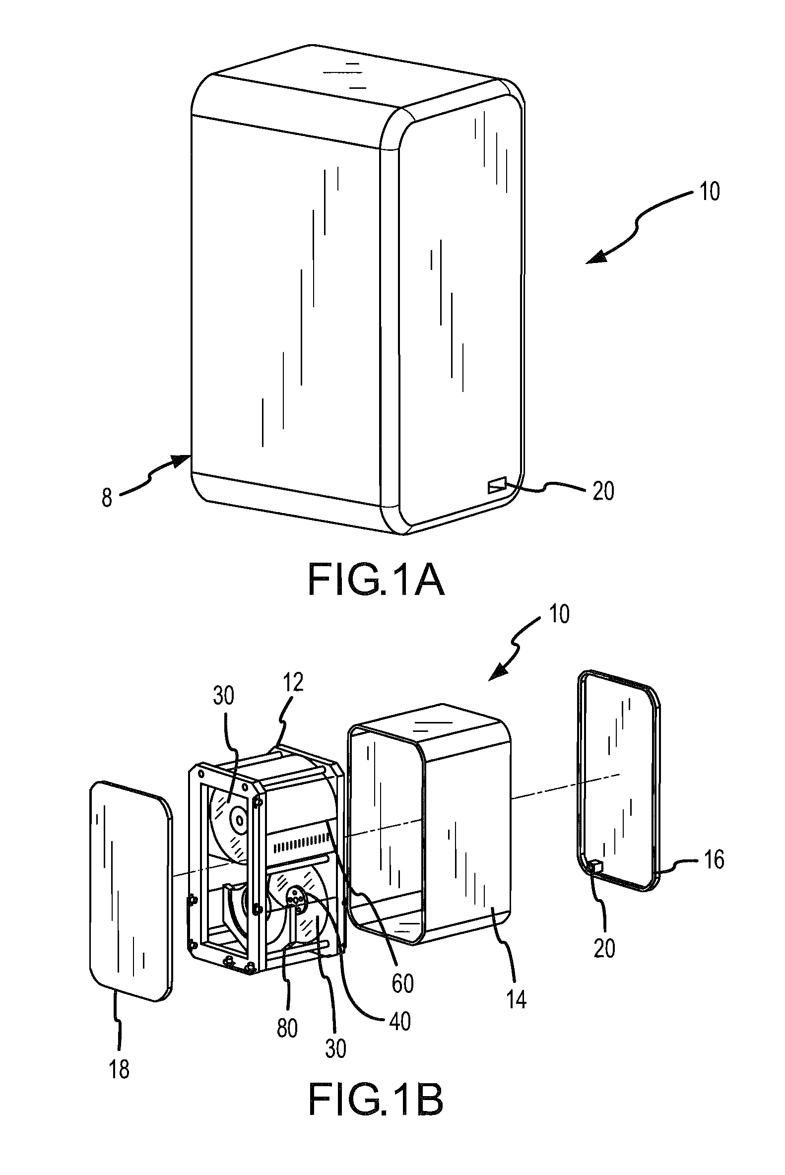
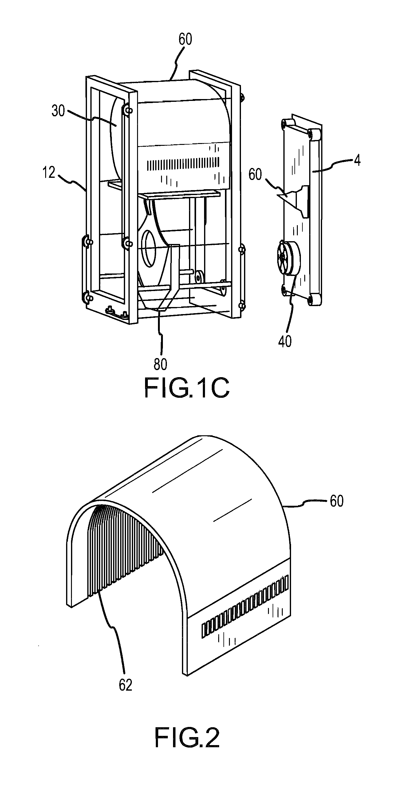
[0057]FIGS. 1A, 1B and 1C illustrate a perspective and two exploded perspective views, respectively, of a multiple disc storage device 10 that provides high capac...


PUM

PropertyMeasurementUnit
radiusaaaaaaaaaa
pressureaaaaaaaaaa
thicknessaaaaaaaaaa

Abstract

A data storage device is provided having a drive hub that may be utilized with a plurality of individual data storage disks that are selectively engageable with the drive hub. In such an arrangement, a plurality of data storage disks may be stored in an inactive state at a storage location and selectively retrieved in an automated process for engagement with the drive hub. Once engaged with the drive hub, data may be accessed from the data storage disk and / or data may be written to the data storage disk. The device allows use of multiple data storage disks with a single drive hub and corresponding sets of read-write heads thereby reducing the per disk cost for storage purposes. The device may be utilized for large scale data storage and / or data back-up applications. In one arrangement, multiple devices may be utilized together in, for example, a RAID configuration.

Description

CROSS REFERENCE TO RELATED APPLICATION [0001] This application claims priority under 35 U.S.C. §119 to U.S. Provisional Application No. 60 / 740,003 entitled: “A Data Storage Device,” having a filing date of Nov. 28, 2005, the contents of which are incorporated herein by reference.FIELD [0002] The present disclosure is directed to computer storage devices. More specifically the present disclosure is directed to computer storage devices having removable data storage disks and storage systems utilizing such devices. BACKGROUND [0003] Most computers use magnetic hard drives for storage of digital information for which immediate access is required. Typically, these magnetic hard drives store the information on rigid disks made of either aluminum or glass. The surfaces of the disks are coated with various thin layers one of which is magnetically alterable. The hard drive also contains read / write heads that are positioned close to the surface of the disk by electronics and firmware in the d...

Claims


Application Information

Patent Timeline
Patent Type & Authority Applications(United States)
IPC IPC(8): G11B17/08G11B19/02
CPCG11B17/225
Inventor BAUCK, RANDALL CLEMENTJONES, DAVID E.
Owner BAUCK RANDALL CLEMENT
Learn More