Pump tower installation structure of liquefied natural gas storage tank and manufacturing method thereof

a technology of liquefied natural gas and installation structure, which is applied in the direction of passenger handling apparatus, transportation and packaging, container discharging methods, etc., can solve the problems of complicated pipe fixing structure and fixing process, and achieve the effect of effective fixing and installation

Active Publication Date: 2019-02-19
SAMSUNG HEAVY IND CO LTD
View PDF22 Cites 0 Cited by
  • Summary
  • Abstract
  • Description
  • Claims
  • Application Information

AI Technical Summary

Benefits of technology

[0026]In the pump tower installation structure of the LNG storage tank according to the embodiment of the present invention and the manufacturing method thereof, the pipes of the pump tower can be effectively fixed and installed at the opening portion formed at the inner hull by the cover and the adaptor.
[0027]Further, since the peripheral portion of the cover insulation board under the cover, which is formed downward from the opening portion, is insulated, the insulation structure of the storage tank can be effectively finished in the inner hull.
[0028]Further, since the adaptor provided to correspond to the remaining area of the opening portion other than the area occupied by the opening portion is installed at the area (gap) generated between the inner hull and the cover, the tolerance problem between the inner hull and the cover can be effectively solved.

Problems solved by technology

However, in this case, since a heat isolating process should be additionally performed in a space formed between the outer hull and the inner hull, a pipe fixing structure and a fixing process may be complicated.
Further, since it is difficult to smoothly finish around the secondary barrier disposed between the inner hull and the primary barrier, a leakage problem may occur.

Method used


Image

  • Pump tower installation structure of liquefied natural gas storage tank and manufacturing method thereof
  • Pump tower installation structure of liquefied natural gas storage tank and manufacturing method thereof
  • Pump tower installation structure of liquefied natural gas storage tank and manufacturing method thereof

Examples


first embodiment

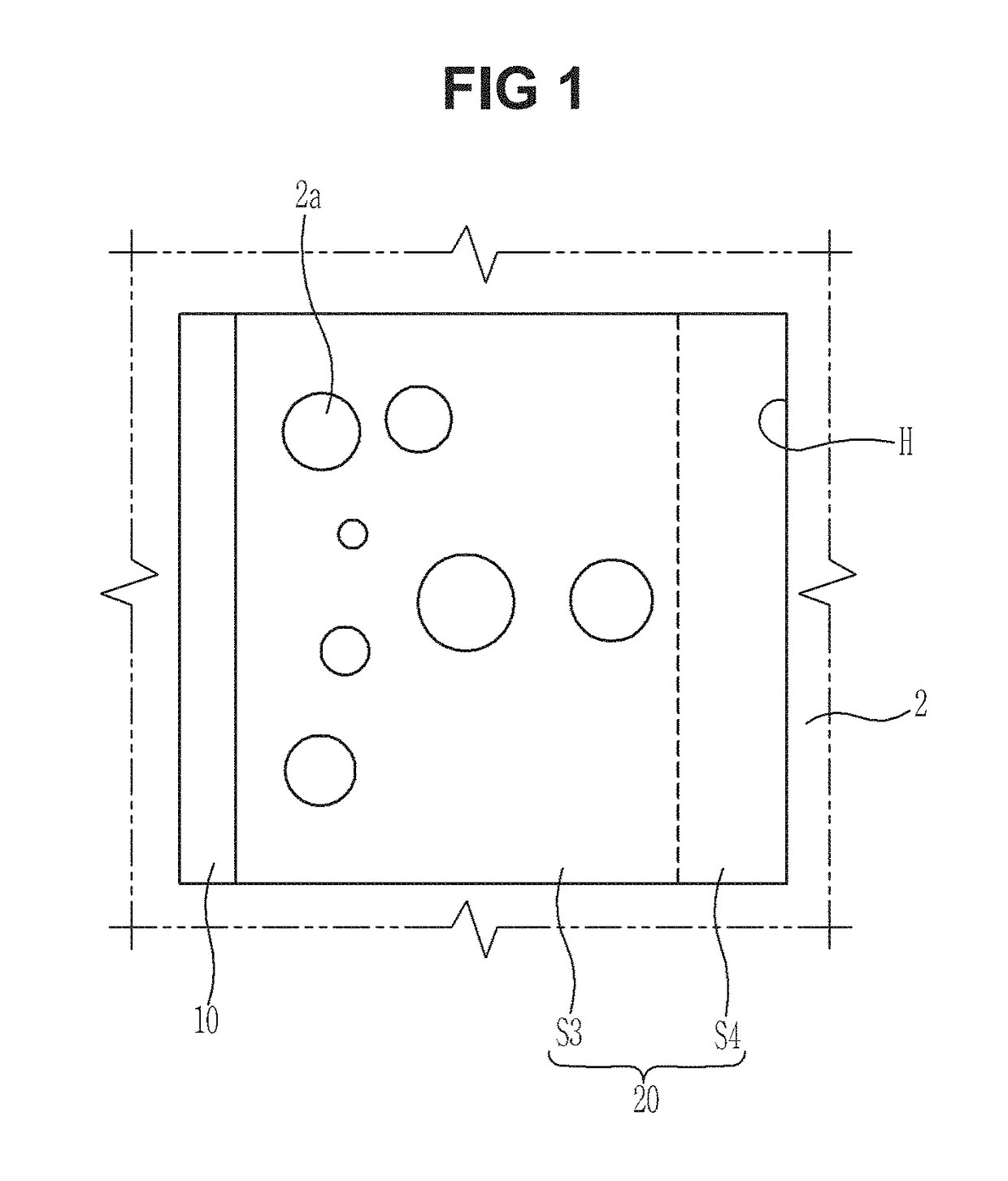
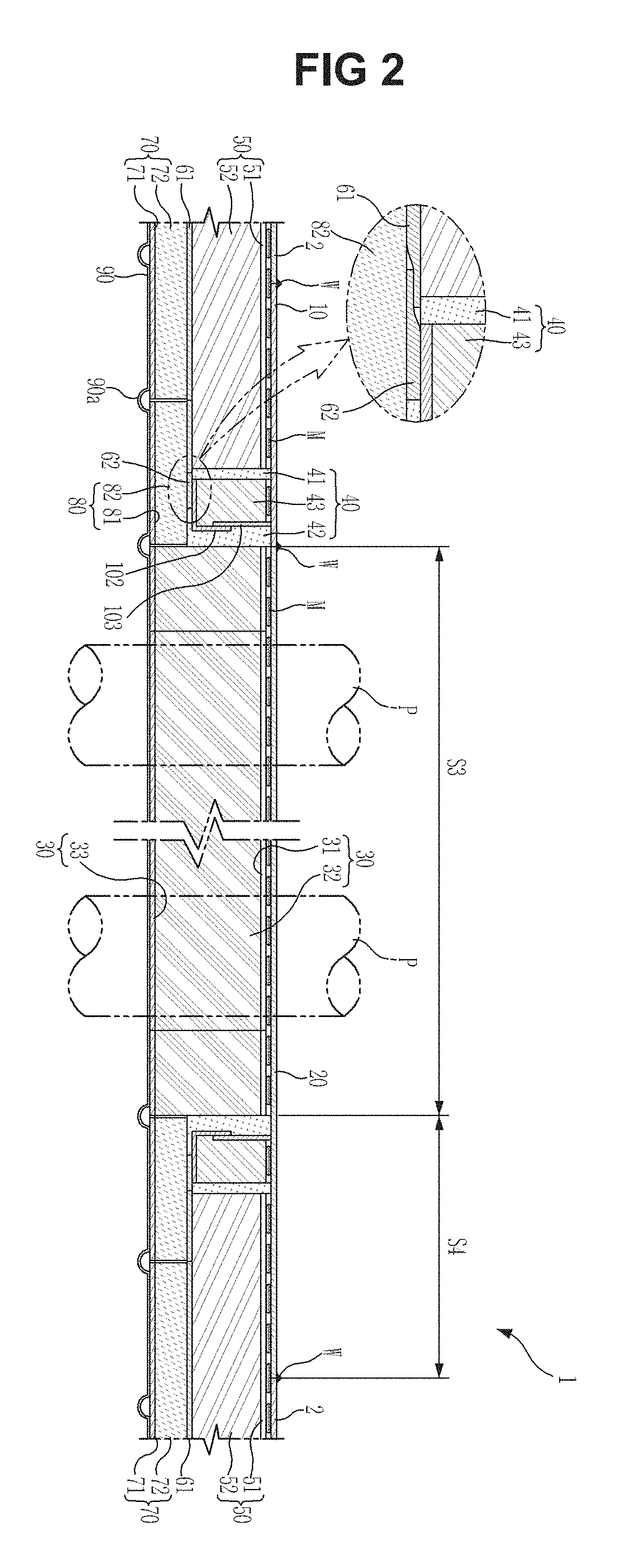
[0036]FIG. 1 is a plane view of a pump tower installation structure of an LNG storage tank in accordance with the present invention, and FIG. 2 is a cross-sectional view of the pump tower installation structure of the LNG storage tank of FIG. 1.

[0037]As illustrated in FIGS. 1 and 2, an LNG storage tank 1 (hereinafter referred to as “storage tank”) according to an embodiment of the present invention has an opening portion H formed at an upper inner hull 2, and a pump tower installed through the opening portion H. The pump tower may be generally configured of a pipe structure having a plurality of pipes, for example, a pipe structure having a plurality of pipes P including two discharge pipes and one filling pipe for loading and unloading liquid cargo, and one emergency pipe. To install the pump tower, the pump tower installation structure of the storage tank 1 according to the embodiment of the present invention includes an adaptor 10, a cover 20, an insulation layer 40, and an adjus...

second embodiment

[0066]FIG. 9 is a plane view of a pump tower installation structure of an LNG storage tank in accordance with the present invention, and FIG. 10 is a cross-sectional view of the pump tower installation structure of the LNG storage tank of FIG. 9.

[0067]As illustrated in FIGS. 9 and 10, an adaptor 10 according to a second embodiment of the present invention is formed in a frame shape having a cover hole portion C to which the cover 20 is bonded, and is fixedly installed around the opening portion H of the inner hull 2. At this time, the adaptor 10 may be bonded to a peripheral portion of the opening portion H (i.e., the inner hull 2) by the welding operation W. The cover hole portion C formed at the adaptor 10 is formed in a through-hole shape corresponding to the cover 20. The cover hole portion C corresponds to the remaining area of the opening portion H other than the predetermined area of the opening portion H occupied by the adaptor 10. The adaptor 10 may be manufactured by a pos...


PUM

PropertyMeasurementUnit
temperaturesaaaaaaaaaa
areaaaaaaaaaaa
thermal contractionaaaaaaaaaa

Abstract

Disclosed herein are a pump tower installation structure of a liquefied natural gas (LNG) storage tank and a manufacturing method thereof. The pump tower installation structure of the LNG storage tank includes an adaptor disposed at a predetermined area of an opening portion formed at an inner hull disposed on an upper side of the LNG storage tank, and a cover having through-holes corresponding to pipes of the pump tower installed at the storage tank, and disposed at a remaining area of the opening portion to be connected with the adaptor.

Description

CROSS-REFERENCE TO RELATED APPLICATIONS[0001]This application is the U.S. National Stage of International Patent Application No. PCT / KR2012 / 009810 filed on Nov. 20, 2012, which claims priority to Korean Patent Application No. 10-2011-0136772 filed on Dec. 16, 2011 and Korean Patent Application No. 10-2012-0123719 filed on Nov. 2, 2012, the disclosures of which are hereby incorporated by reference in their entireties.TECHNICAL FIELD[0002]Embodiments of the present invention relate to a pump tower installation structure of a liquefied natural gas (LNG) storage tank and a manufacturing method thereof.BACKGROUND ART[0003]An LNG storage tank of an LNG carrier generally stores LNG cooled to a temperature of approximately −163° C., and thus is manufactured of a material which may withstand cryogenic temperatures, and has an insulation structure which is strong against thermal stress and thermal contraction and may prevent heat penetration. The LNG storage tank includes a primary barrier, a...

Claims


Application Information

Patent Timeline
Patent Type & Authority Patents(United States)
IPC IPC(8): F17C1/12F17C13/00B63B19/00F17C3/04B63B27/24B63B25/16E04H7/02
CPCF17C13/00B63B19/00B63B25/16B63B27/24F17C3/04E04H7/02Y10T29/49826F17C2203/035F17C2205/0355F17C2209/227F17C2209/232F17C2223/0161F17C2223/033F17C2201/052F17C13/004F17C13/06F17C2270/0107F17C2221/033F17C3/027F17C2203/0358F17C2201/0157
Inventor CHUN, SANG-EONKIM, DAE-JUNGPARK, SUNG-OHLEE, SOO-HOJOH, KI-HUNHWANG, JEONG-OHBANG, CHANG-SEON
Owner SAMSUNG HEAVY IND CO LTD
Why Eureka
Try Eureka