Spinal stabilization using bone anchor seat and cross coupling with improved locking feature

a technology of spine and cross coupling, which is applied in the field of vertebral stabilization of the spine, can solve the problems of compromising the quality of life of a person, the most common and often debilitating conditions affecting millions of people, and back pain

Active Publication Date: 2006-10-12
ALTUS PARTNERS
View PDF37 Cites 136 Cited by
  • Summary
  • Abstract
  • Description
  • Claims
  • Application Information

AI Technical Summary

Benefits of technology

[0013] In accordance with one or more embodiments of the present invention, a stabilization system for implantation in a patient includes: a first pivot element including at least one first aperture, a first engagement element, and a first locking element; a second pivot element including at least one second aperture, a second engagement element, and a second locking element, wherein: the first and second apertures are sized, shaped and disposed in substantial axial alignment such that they are operable to receive the stabilization rod therethrough, and displacement of the first and second locking elements relative to one another urges the first and second apertures to misalign and thereby cl...

Problems solved by technology

Back pain is one of the most common and often debilitating conditions affecting millions of people in all walks of life.
Approximately half of those suffering from persistent back pain are afflicted with chronic disabling pain, which seriously compromises a person's quality of life and is the second most common cause of worker absenteeism.
Further, the cost of treating chronic back pain is very high, even though the majority of sufferers do not receive treatment due to health risks, limited treatment options and inadequate therapeutic results.
Thus, chronic back pain has a significantly adverse effect on a person's quality of life, on industrial productivity, and on heath care expenditures.
However, in many cases, and in particular, in cases involving fusion across the lumbosacral articulation and when there are many levels involved, pseudoarthrosis is a problem.
However, following the surgica...

Method used


Image

  • Spinal stabilization using bone anchor seat and cross coupling with improved locking feature
  • Spinal stabilization using bone anchor seat and cross coupling with improved locking feature
  • Spinal stabilization using bone anchor seat and cross coupling with improved locking feature

Examples


Embodiment Construction

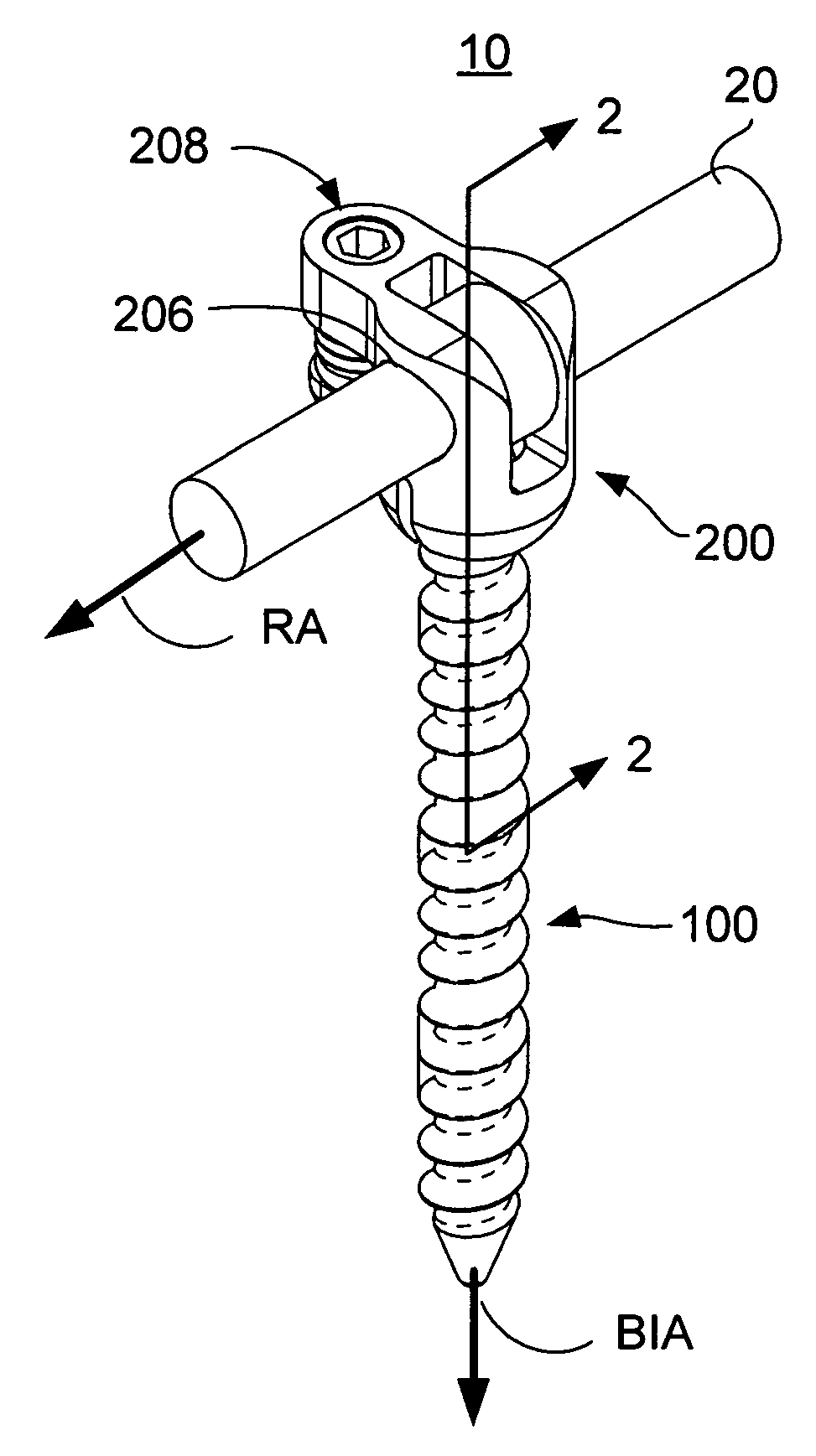
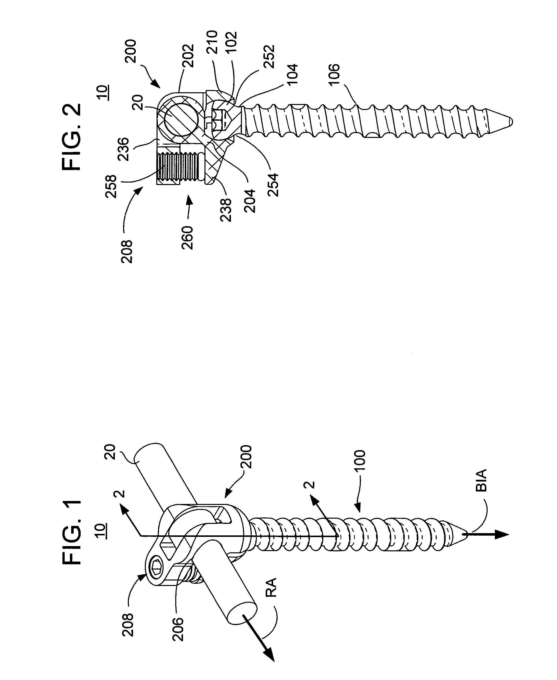
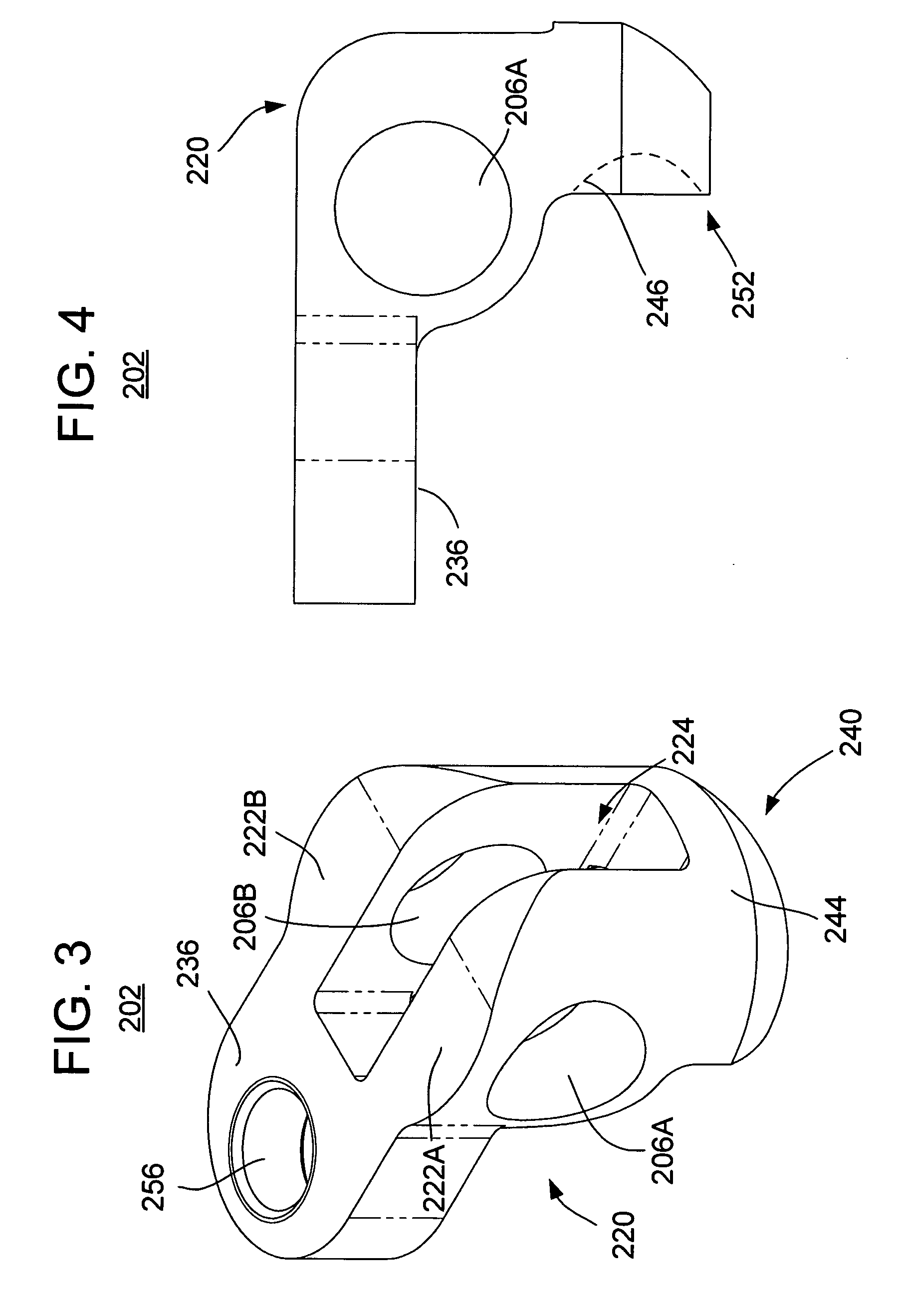
[0053]FIGS. 1-7 illustrate an embodiment of a spinal stabilizer system 10 in accordance with one or more aspects of the present invention. In use, it is understood that a plurality of the stabilizing systems 10 (e.g., pairs thereof) may secure one or more elongate elements, such as one or more stabilization rods (longitudinally oriented and / or cross-rods), cross-link elements, etc., for internal fixation of respective bones of a patient, such as vertebrae of the spine.

[0054] The system 10 includes an anchor 100 and an anchor seat (or tulip) 200 that cooperate to fix a portion of an elongate element, such as stabilization rod 20, to a bone. The bone anchor 100 includes a head 102, a neck 104, and a shaft 106, where the neck 104 interconnects the head 102 and the shaft 106. The shaft 106 extends away from the head 102 and is operable for connection to the bone of the patient. For example, the shaft 106 may include threads that may engage a bore made in the bone such that the anchor 1...


PUM


Abstract

A stabilization rod engaging apparatus for implantation in a patient includes: a first pivot element including at least one first aperture, a first engagement element, and a first locking element; a second pivot element including at least one second aperture, a second engagement element, and a second locking element, wherein: the first and second apertures are sized, shaped and disposed in substantial axial alignment such that they are operable to receive the stabilization rod therethrough, and displacement of the first and second locking elements relative to one another urges the first and second apertures to misalign and thereby clamp the stabilization rod.

Description

CROSS REFERENCE TO RELATED APPLICATIONS [0001] This application claims the benefit of U.S. Provisional Patent Application No. 60 / 658,227, filed Mar. 3, 2005, the entire disclosure of which is hereby incorporated by reference.BACKGROUND OF THE INVENTION [0002] The present invention is directed to vertebral stabilization of a spine using one or more rods anchored onto the vertebrae. [0003] Back pain is one of the most common and often debilitating conditions affecting millions of people in all walks of life. Today, it is estimated that over ten million people in the United States alone suffer from persistent back pain. Approximately half of those suffering from persistent back pain are afflicted with chronic disabling pain, which seriously compromises a person's quality of life and is the second most common cause of worker absenteeism. Further, the cost of treating chronic back pain is very high, even though the majority of sufferers do not receive treatment due to health risks, limit...

Claims


Application Information

Patent Timeline
IPC IPC(8): A61F2/30
CPCA61B2017/7073A61B17/7049A61B17/7041A61B17/7037
Inventor ALBERT, TODD JAMESZUBOK, RAFAILKVITNITSKY, MIKHAIL
Owner ALTUS PARTNERS
Why Eureka
Try Eureka