Method and apparatus for providing a retainer for a bone stabilization device

a bone stabilization device and retainer technology, applied in the field of screw retainer for bone plate, can solve the problems of compromising the quality of life of a person, the most common and often debilitating conditions affecting millions of people, and back pain

Inactive Publication Date: 2006-10-12
ACCELERATED INNOVATION
View PDF17 Cites 69 Cited by
  • Summary
  • Abstract
  • Description
  • Claims
  • Application Information

AI Technical Summary

Problems solved by technology

Back pain is one of the most common and often debilitating conditions affecting millions of people in all walks of life.
Approximately half of those suffering from persistent back pain are afflicted with chronic disabling pain, which seriously compromises a person's quality of life and is the second most common cause of worker absenteeism.
Further, the cost of treating chronic back pain is very high, even though the majority of sufferers do not receive treatment due to health risks, limited treatment options and inadequate therapeutic results.
Thus, chronic back pain has a significantly adverse effect on a person's quality of life, on industrial productivity, and on heath care expenditures.
However, following the surgical procedure, fusion takes additional time to achieve maximum stability and a spinal fixation device is typically used to support the spinal column until a desired level of fusion is achieved.
In some cases the screws may be self-tapping.
One of the problems associated with this technique is the tendency of screws or other fasteners to gradually work loose after fixation.
Slight shock or vibration of the vertebrae, due to walking, climbing stairs or more vigorous activity by the patient following treatment increases this tendency, jeopardizing the integrity of fixation.
Moreover, as the fasteners work loose, the outward protrusion of the heads over other components of the fasteners can be a source of discomfort and present the risk of trauma to adjacent and surrounding soft tissue.
Screws sufficiently short to avoid interfering with one another may not be long enough to assure a secure plate fixation.
Further, the physician may encounter difficulties in positioning the plate if one of the vertebrae, due to a particular shape and orientation, cannot readily retain a perpendicularly inserted fastener.
Among the disadvantages of this design is the weakening of the plate in the area of the apertures due to the receiving grooves.
This weakening may cause failure of the device under loading conditions.
A disadvantage of this approach to securing the screws is again the requirement for a recess or groove in the area of the aperture to accommodate the deformable retaining feature.
Further, as the retaining feature must be bent (past its point of elasticity) there is the possibility of breaking the retaining feature during the surgery.
Depending on when the breakage occurs, this might require the removal of a number of screws that have already been tightened down, a very undesirable necessity.
The screw removal problem is exacerbated by the retainer feature itself, as it cannot be easily reversed.
Indeed, once deformed, the cold work of the material makes it more difficult to reverse the deformation process to remove the screws.
Therefore, conventional devices for screw retention have not provided a comprehensive, simple, and reliable means of counteracting the tendency of the bone screws to work loose after cervical plate fixation.

Method used


Image

  • Method and apparatus for providing a retainer for a bone stabilization device
  • Method and apparatus for providing a retainer for a bone stabilization device
  • Method and apparatus for providing a retainer for a bone stabilization device

Examples


Embodiment Construction

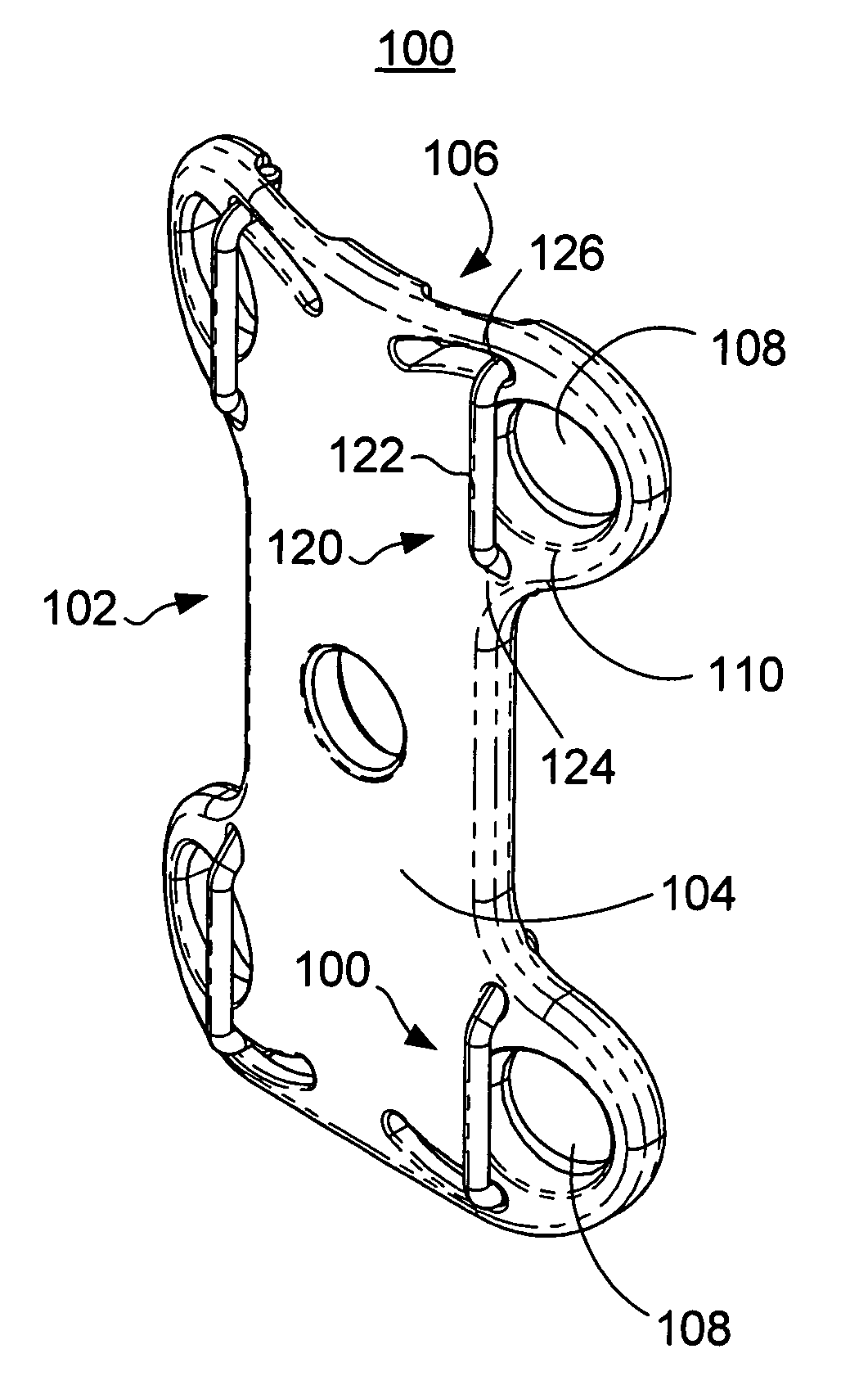
[0029] It is noted that various aspects of the present invention may be employed in any application in which a screw (or other attachment device) is used to fasten a structure to an anatomical body. For the purposes of discussion, and not by way of limitation, various aspects of the present invention will be presented in connection with a number of embodiments directed to a specific application in which spinal stabilization (e.g., fusion) is desired.

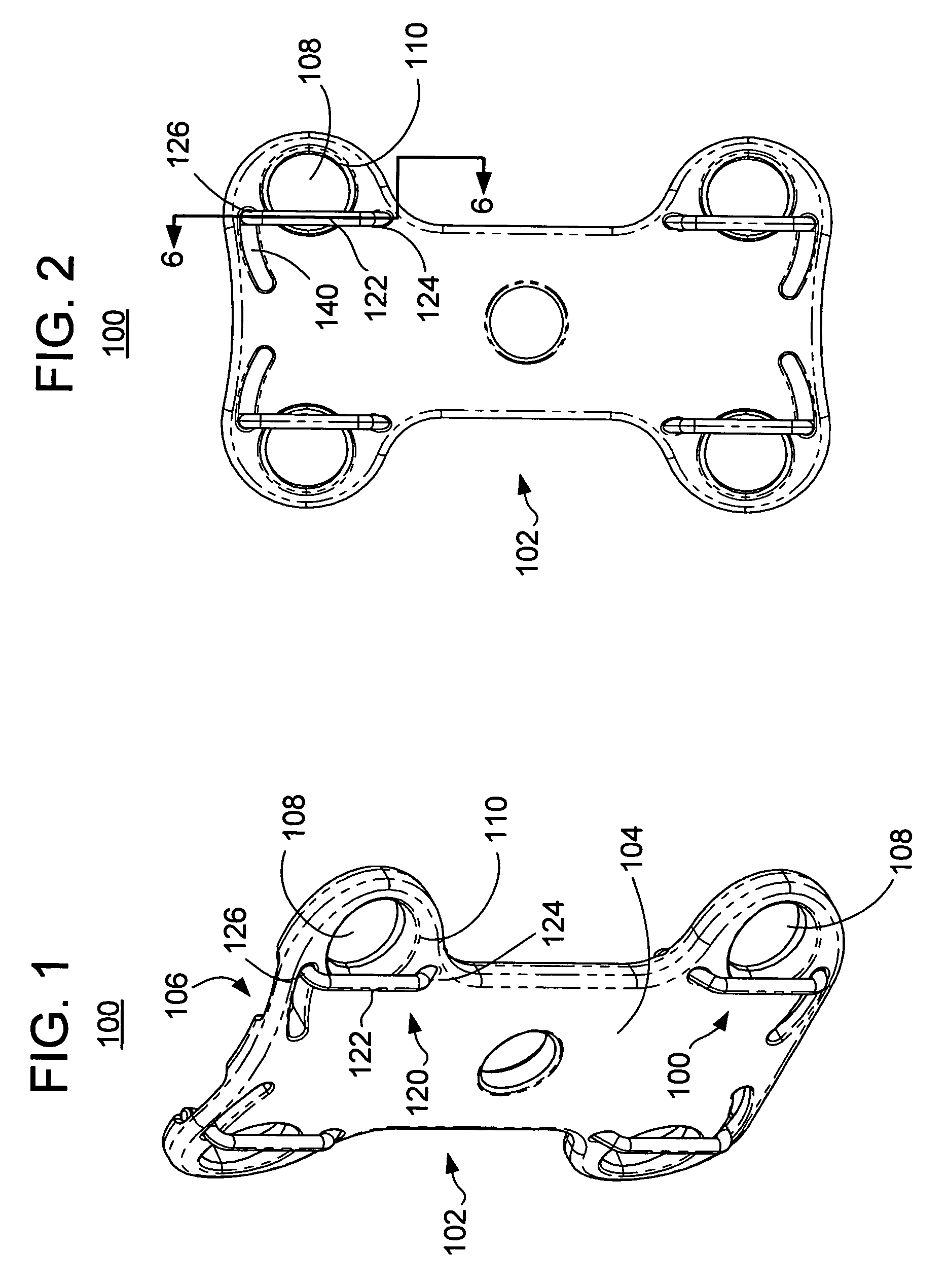
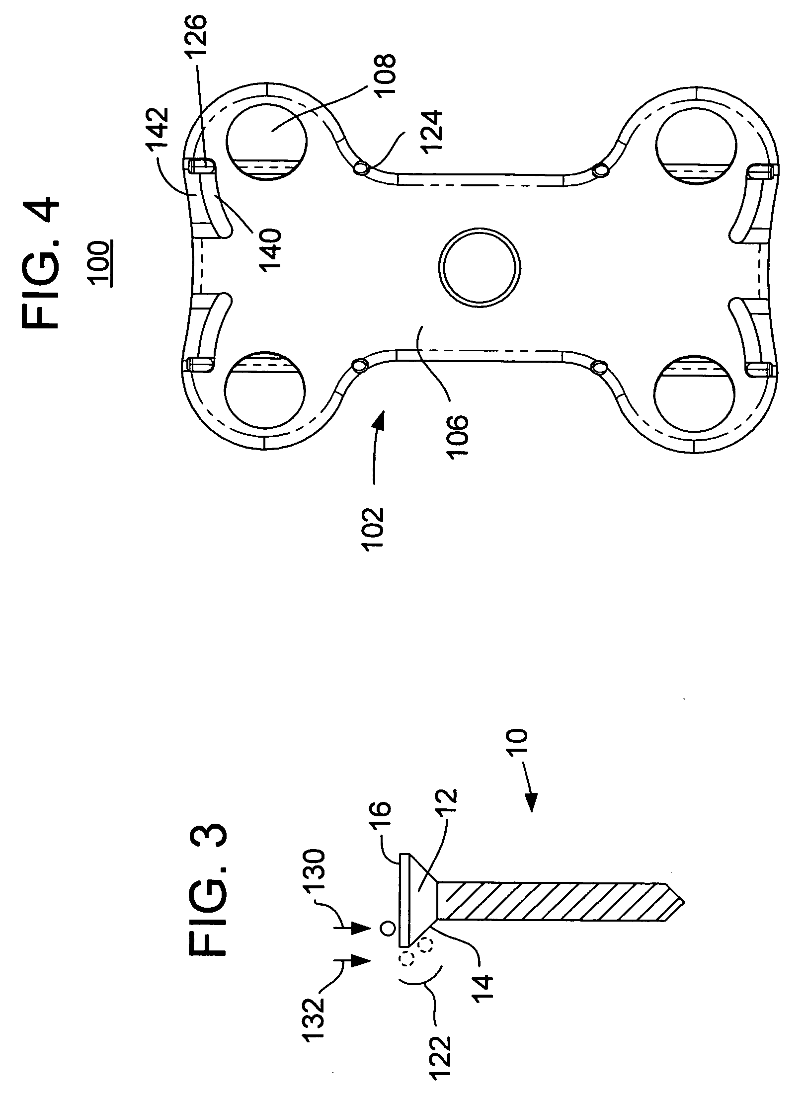
[0030] In this regard, reference is now made to the drawings, wherein like numerals indicate like elements. There is shown in FIGS. 1-6 a skeletal fixation apparatus in accordance with one or more embodiments of the present invention. The skeletal fixation apparatus in this embodiment is implemented as a bone plate 100 that is suitable for use in fusing adjacent vertebrae in a spine. It is understood that the bone plate 100 may be employed at any level of the spine (cervical, thoracic, lumbar) by suitable adjustment in the various dimen...


PUM


Abstract

A skeletal fixation apparatus includes: a plate having first and second spaced apart surfaces and a plurality of apertures extending through the surfaces of the plate, each aperture for receiving a respective fixation element for coupling the plate to one or more bones of a patient; and at least one retention element having an elongate member coupled to the plate at first and second ends thereof, wherein the first end of the elongate member is fixed in position and the second end of the elongate member is operable to rotate about the first end such that: (i) at least a portion of the elongate member overlies at least a portion of a first of the apertures when the second end is in at least one first rotational position to retain a first fixation element in the first aperture, and (ii) the elongate member does not substantially overlie the first aperture when the second end is in at least one second rotational position to permit the first fixation element to enter or exit the first aperture.

Description

CROSS REFERENCE TO RELATED APPLICATIONS [0001] This application claims the benefit of U.S. Provisional Patent Application No. 60 / 658,313, filed Mar. 3, 2005, the entire disclosure of which is hereby incorporated by reference.BACKGROUND OF THE INVENTION [0002] The present invention is directed to a screw retainer for a bone plate. [0003] Back pain is one of the most common and often debilitating conditions affecting millions of people in all walks of life. Today, it is estimated that over ten million people in the United States alone suffer from persistent back pain. Approximately half of those suffering from persistent back pain are afflicted with chronic disabling pain, which seriously compromises a person's quality of life and is the second most common cause of worker absenteeism. Further, the cost of treating chronic back pain is very high, even though the majority of sufferers do not receive treatment due to health risks, limited treatment options and inadequate therapeutic resu...

Claims


Application Information

Patent Timeline
Patent Type & Authority Applications(United States)
IPC IPC(8): A61F2/30
CPCA61B17/8042
Inventor ROTHMAN, RICHARD H.ZUBOK, RAFAILKVITNITSKY, MIKHAIL
Owner ACCELERATED INNOVATION
Why Eureka
Try Eureka