Information display system
a technology of information display and display system, applied in the direction of distance measurement, navigation instruments, instruments, etc., can solve the problem of not being able to accurately realize the situation of users
- Summary
- Abstract
- Description
- Claims
- Application Information
AI Technical Summary
Problems solved by technology
Method used
Image

Examples
first embodiment
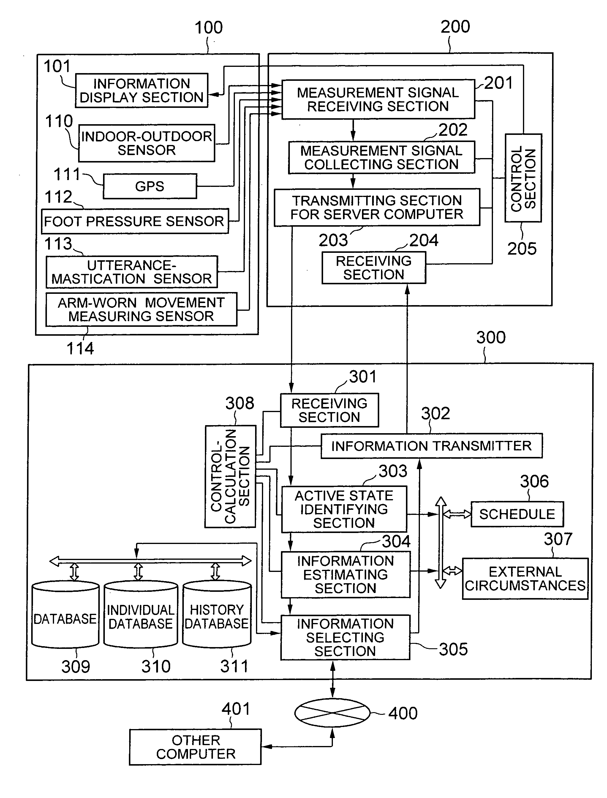
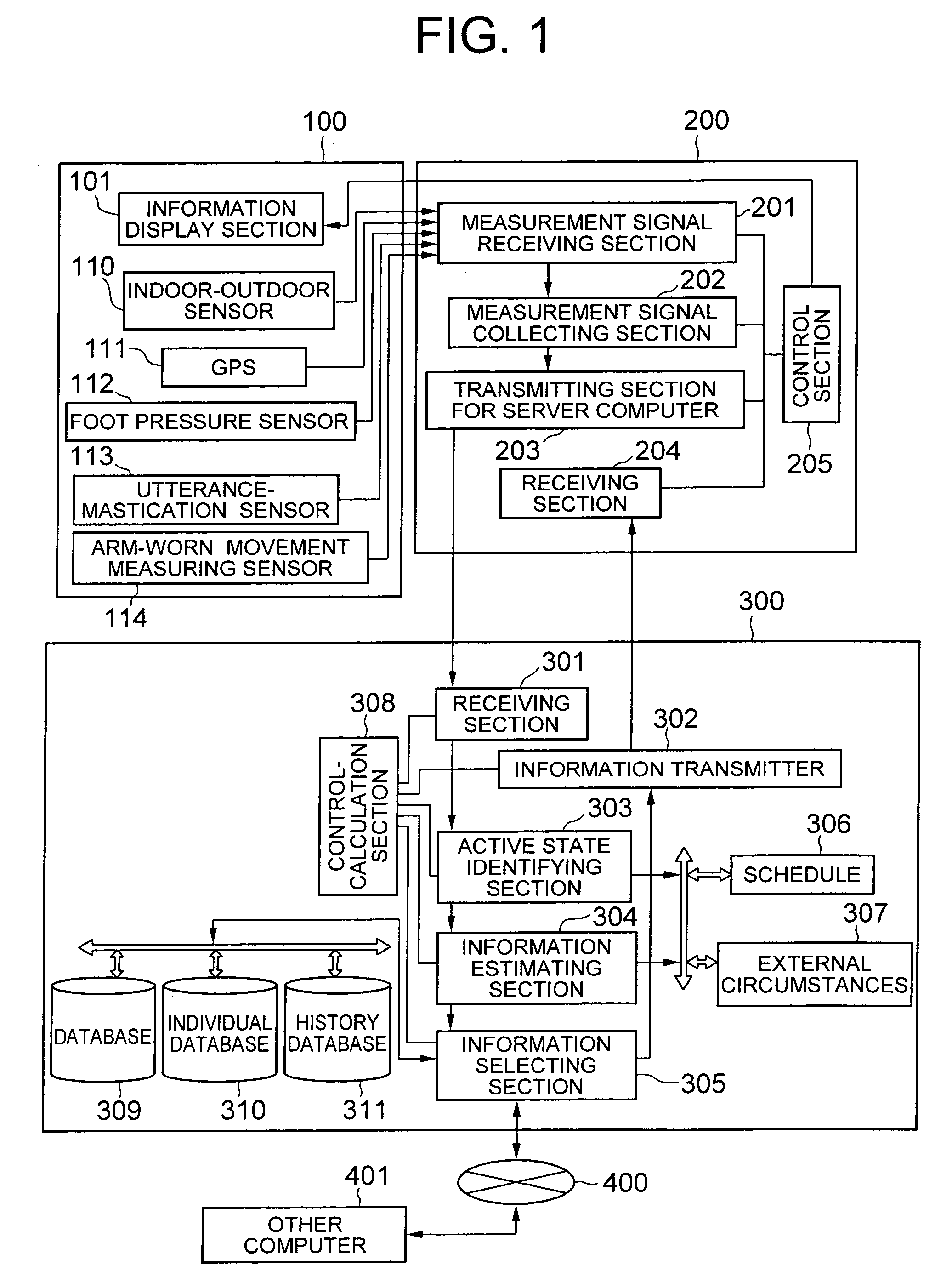
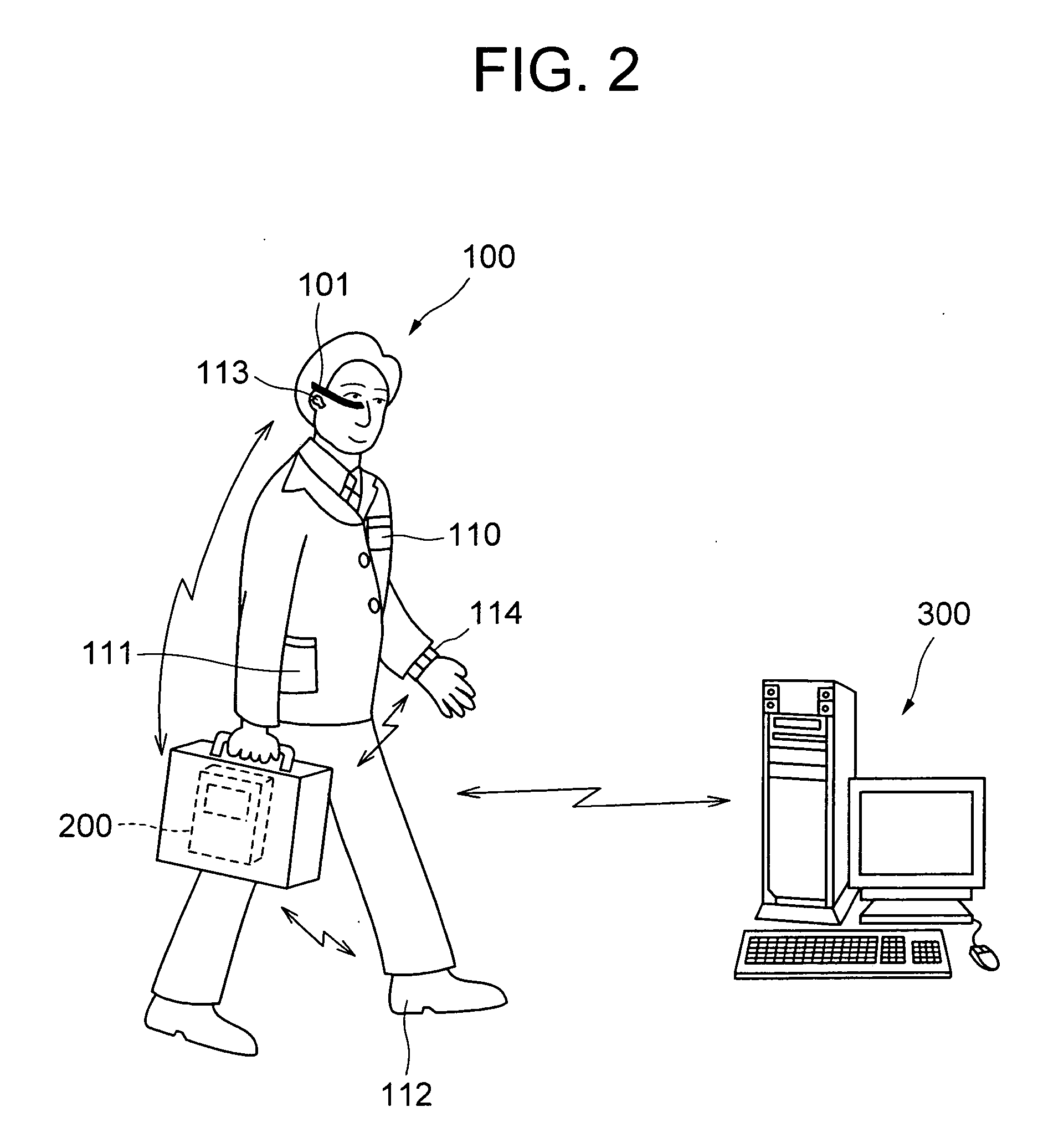
[0044]FIG. 1 shows a functional block of an information display system according to a first embodiment. This information display system includes a group of various sensors worn by a user 100, a mobile gateway 200, and a server computer 300. FIG. 2 shows a schematic structure of the information display system.
[0045] First of all, a group of devices and sensors worn by the user 100 will be described. The user 100 is wearing on a body an indoor-outdoor sensor 110, a GPS (Global Positioning System) 111, a foot pressure sensor 112, an utterance-mastication sensor 113, and an arm-worn movement measuring sensor 114. Hereinafter, these sensors will be called as “sensor 110 etc”. The sensor 110 etc. corresponds to a measuring means. Moreover, the user 100 wears an information display section 101 near one of eyes on head. A schematic structure and a function of the indoor-outdoor sensor 110, the GPS 111, the foot pressure sensor 112, the utterance-mastication sensor 113, and the arm-worn mov...
second embodiment
[0180] An information display system according to a second embodiment of the present invention will be described. FIG. 22 shows a schematic structure of the information display system according to the second embodiment. In the first embodiment, the measurement signals from the sensor 110 etc. are transmitted to the server computer 300 via the mobile gateway 200. Moreover, the information provided from the server computer 300 is transmitted to the MEG 101 of the user 100 via the mobile gateway 200. Whereas, the second embodiment differs from the first embodiment at a point that a notebook (laptop) personal computer 450 serves functions of both the mobile gateway 200 and the server computer 300. The same reference numerals are used for sections same as in the first embodiment, and repeated description is omitted.
[0181]FIG. 23 shows functional blocks of the information display system according to the second embodiment. This information display system includes a group of sensors worn b...
modified embodiment
[0219] An information display system according to a modified embodiment of the present invention will be described. The same reference numerals are used for sections same as in the first and the second embodiment, and repeated description is omitted. FIG. 32 shows a schematic structure of the information display system according to the modified embodiment. In this information display system, lifestyle habits of the user 100 can be monitored.
[0220] The user 100 wears sensors such as the indoor-outdoor sensor 110, the GSP 111, the foot pressure sensor 112, the utterance-mastication sensor 113, and a pulse and blood pressure sensor 3201. The pulse and blood pressure sensor 3201 is a wrist watch type sensor to be worn on an arm. The pulse and blood pressure sensor 3201 detects a pulse rate, a pulse speed, regularity and irregularity, and a blood pressure. The measurement signals from the sensor 110 etc. are transmitted to a monitor terminal 500. Based on the measurement signals, the li...
PUM
 Abstract
Description
Claims
Application Information
 - R&D
- Intellectual Property
- Life Sciences
- Materials
- Tech Scout
- Unparalleled Data Quality
- Higher Quality Content
- 60% Fewer Hallucinations
Browse by: Latest US Patents, China's latest patents, Technical Efficacy Thesaurus, Application Domain, Technology Topic, Popular Technical Reports.
© 2025 PatSnap. All rights reserved.Legal|Privacy policy|Modern Slavery Act Transparency Statement|Sitemap|About US| Contact US: help@patsnap.com