Variable geometry turbocharger

Inactive Publication Date: 2006-10-19
SEMRAU H ALBERT
View PDF15 Cites 23 Cited by
  • Summary
  • Abstract
  • Description
  • Claims
  • Application Information

AI Technical Summary

Benefits of technology

[0011] Yet another aspect of the present invention is to provide a turbocharger subassembly comprising a housing, a blade wheel and a single rotating member. The housing has an interior, an inlet for allowing fluid to enter the interior and an outlet for allowing the fluid to exit the housing. The blade wheel is in the housing. The single rotating member surrounds the blade wheel within the housing and is positioned between the inlet and the blade

Problems solved by technology

A limiting factor in the performance of an internal combustion engine is the amount of combustion air that can be delivered to the intake manifold for combustion in the engine cylinders.
Atmospheric pressure is often inadequate to supply the required amount of air for proper operation of an engine.
Sizing a turbocharger for proper performance under all engine operating conditions can be difficult.
However, if the engine is to be operated at significantly less than full load for extended periods of time, it becomes more difficult to design a turbocharger that will perform well thro

Method used


Image

  • Variable geometry turbocharger
  • Variable geometry turbocharger
  • Variable geometry turbocharger

Examples


Embodiment Construction

[0030] For purposes of description herein, the terms “upper,”“lower,”“right,”“left,”“rear,”“front,”“vertical,”“horizontal,” and derivatives thereof shall relate to the invention as orientated in FIG. 1. However, it is to be understood that the invention may assume various alternative orientations, except where expressly specified to the contrary. It is also to be understood that the specific devices and processes illustrated in the attached drawings, and described in the following specification are simply exemplary embodiments of the inventive concepts defined in the appended claims. Hence, specific dimensions and other physical characteristics relating to the embodiments disclosed herein are not to be considered as limiting, unless the claims expressly state otherwise.

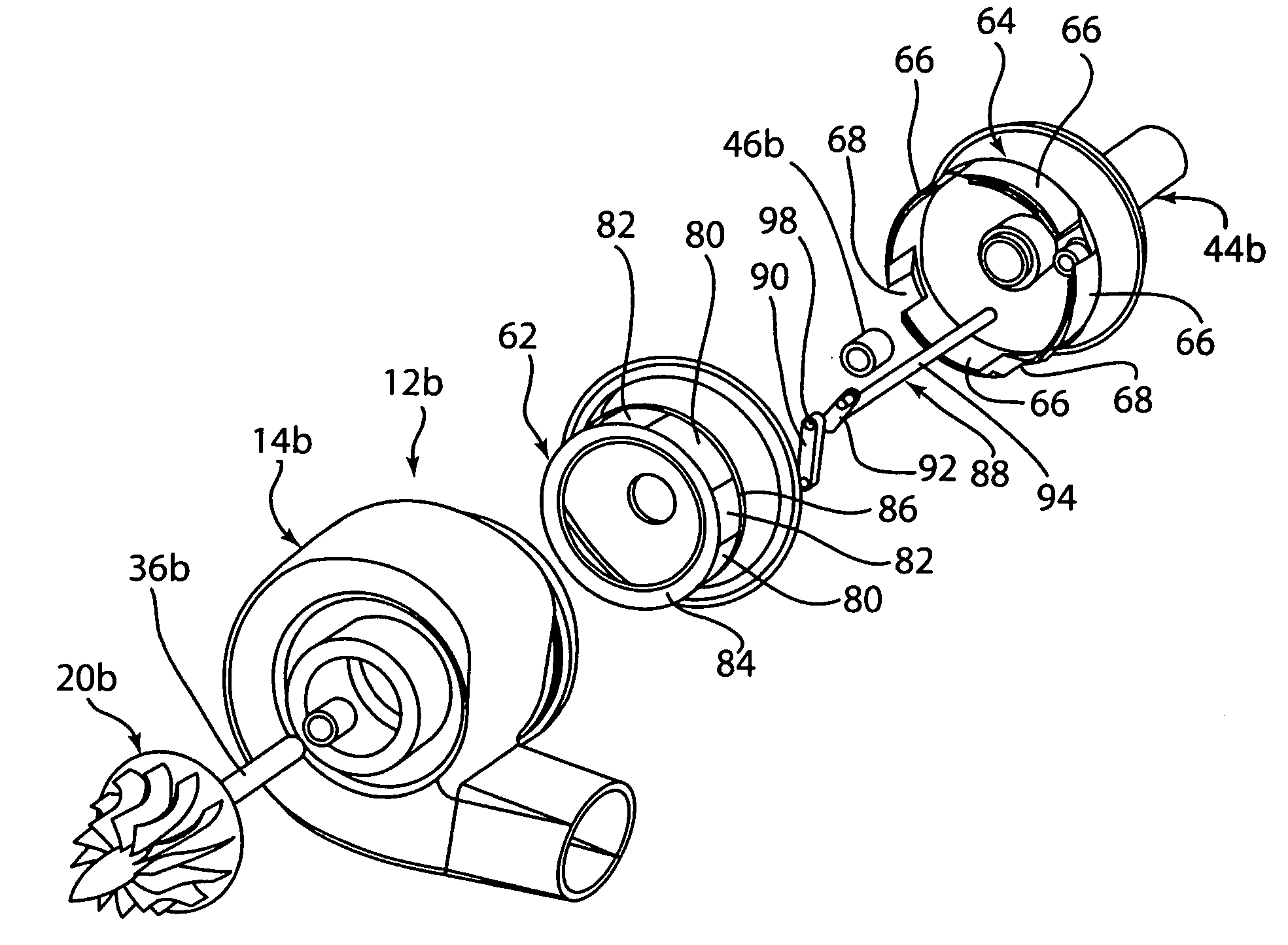
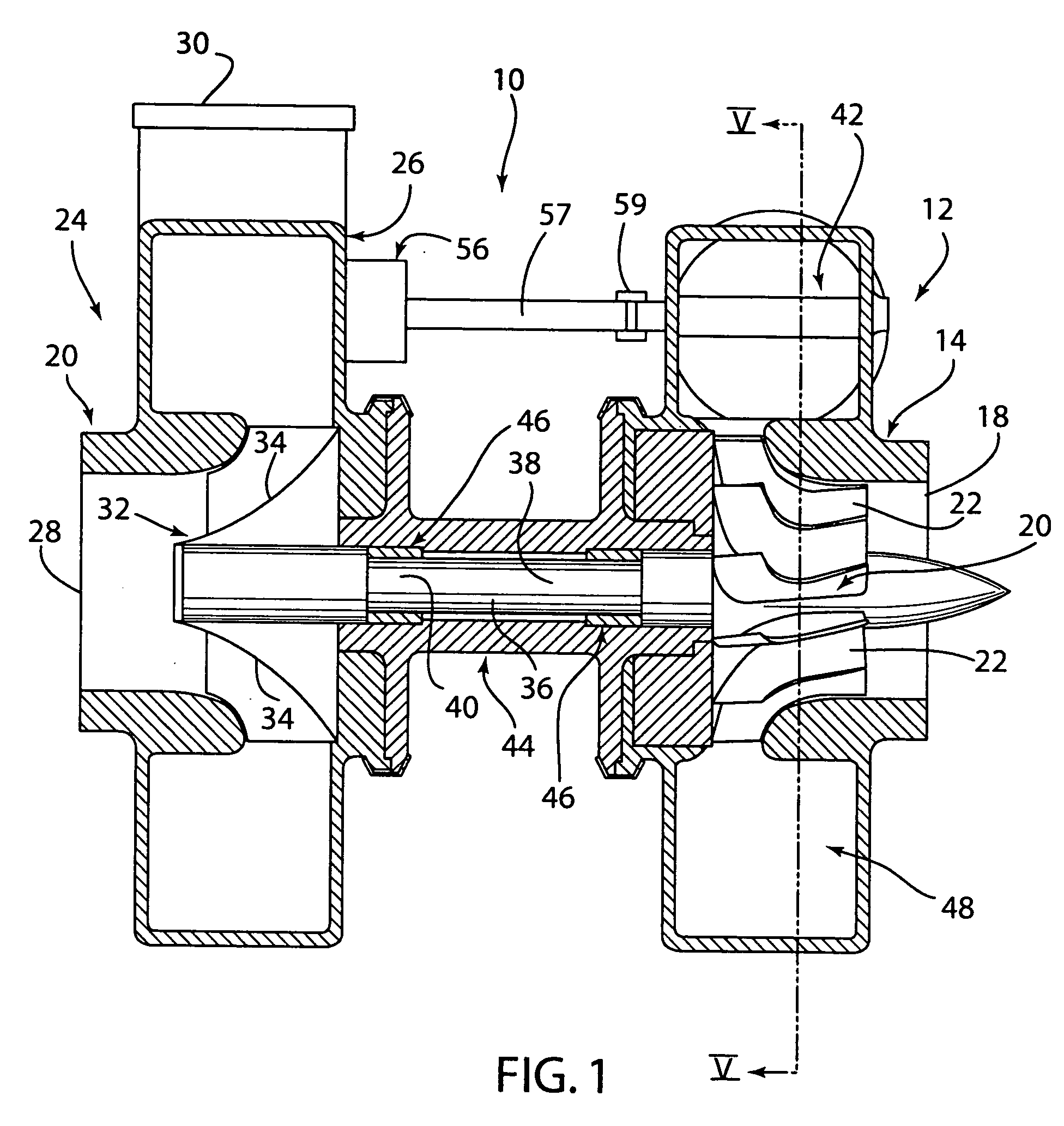
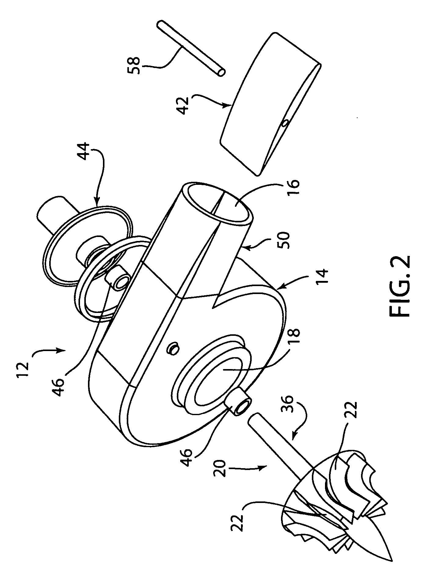
[0031] The reference number 10 (FIGS. 1-2) generally designates a turbocharger assembly embodying the present invention. In the illustrated example, the turbocharger assembly 10 comprises a turbine 12 including a tur...


PUM


Abstract

A turbine comprising a housing, a turbine wheel and at least one movable member. The housing has an interior, an inlet for allowing fluid to enter the interior and an outlet for allowing the fluid to exit the housing. The turbine wheel has turbine blades located in the housing. The at least one movable member is located within the housing and is positioned in a fluid path between the inlet and the turbine blades for selectively controlling a flow of fluid to the turbine blades in the housing.

Description

FIELD OF THE INVENTION [0001] The present invention relates to turbine engines and, more particularly, pertains to a variable geometry turbine. BACKGROUND OF THE INVENTION [0002] A limiting factor in the performance of an internal combustion engine is the amount of combustion air that can be delivered to the intake manifold for combustion in the engine cylinders. Atmospheric pressure is often inadequate to supply the required amount of air for proper operation of an engine. [0003] An internal combustion engine may include one or more turbochargers for compressing a fluid to be supplied to one or more combustion chambers within corresponding combustion cylinders. Each turbocharger typically includes a turbine driven by exhaust gases from the engine, and a compressor driven by the turbine. The compressor receives the fluid to be compressed and supplies the compressed fluid to the combustion chambers. The fluid compressed by the compressor may be in the form of combustion air only, or ...

Claims


Application Information

Patent Timeline
IPC IPC(8): F02D23/00
CPCF01D17/141F01D17/146F01D17/16F02B37/22F05D2260/50Y02T10/144F05D2220/40F05D2260/56F02B37/24Y02T10/12
Inventor SEMRAU, H. ALBERT
Owner SEMRAU H ALBERT
Why Eureka
Try Eureka