Method for friction stir welding, jig therefor, member with friction stir-welded portion, and tool for friction stir welding

a friction stir welding and welding apparatus technology, applied in the direction of soldering equipment, manufacturing tools, auxilary welding devices, etc., can solve the problems of high welding cost, increased material cost, complex structure of friction stir welding apparatus, etc., and achieve the effect of promoting plastic material flow

Inactive Publication Date: 2006-10-19
HONDA MOTOR CO LTD
View PDF3 Cites 20 Cited by
  • Summary
  • Abstract
  • Description
  • Claims
  • Application Information

AI Technical Summary

Benefits of technology

[0017] To eliminate the above drawback, so-called coaxial alignment may be formed in advance to align the axis L1 and the axis L2 with each other as much as possible. However, coaxial alignment requiring precision is complicated. If the axes are brought out of alignment with each other due to some disturbance after a coaxial alignment process has been finished, then another coaxial alignment process has to be performed again. Accordingly, the efficiency of the friction stir welding process is lowered.
[0054] If the first screw section and the second screw section have equal screw pitches, and the first screw section and the second screw section have equal axial lengths, then a downward force produced by the first screw section and an upward force produced by the second screw section are brought into balance. The workpieces are thus prevented from being lifted or lowered, and plastic material flow by the first screw section and plastic material flow by the second screw section are caused in balance, promoting plastic material flow near the boundary line between the first screw section and the second screw section.

Problems solved by technology

The technology disclosed in Patent Document 2 is disadvantageous in that since the two friction stir welding tools need to be installed in opposite directions, the friction stir welding apparatus is complex in structure and the facility investment is expensive.
The technology disclosed in Patent Document 3 results in an increase in the material cost and hence the friction stir welding cost on account of the need for the additional material piece.
In addition, because there is a need for a mechanism for supplying the additional material piece, the friction stir welding apparatus is also complex in structure and the facility investment is also expensive.

Method used


Image

  • Method for friction stir welding, jig therefor, member with friction stir-welded portion, and tool for friction stir welding
  • Method for friction stir welding, jig therefor, member with friction stir-welded portion, and tool for friction stir welding
  • Method for friction stir welding, jig therefor, member with friction stir-welded portion, and tool for friction stir welding

Examples


first embodiment

[0088] First, a first embodiment will be described below.

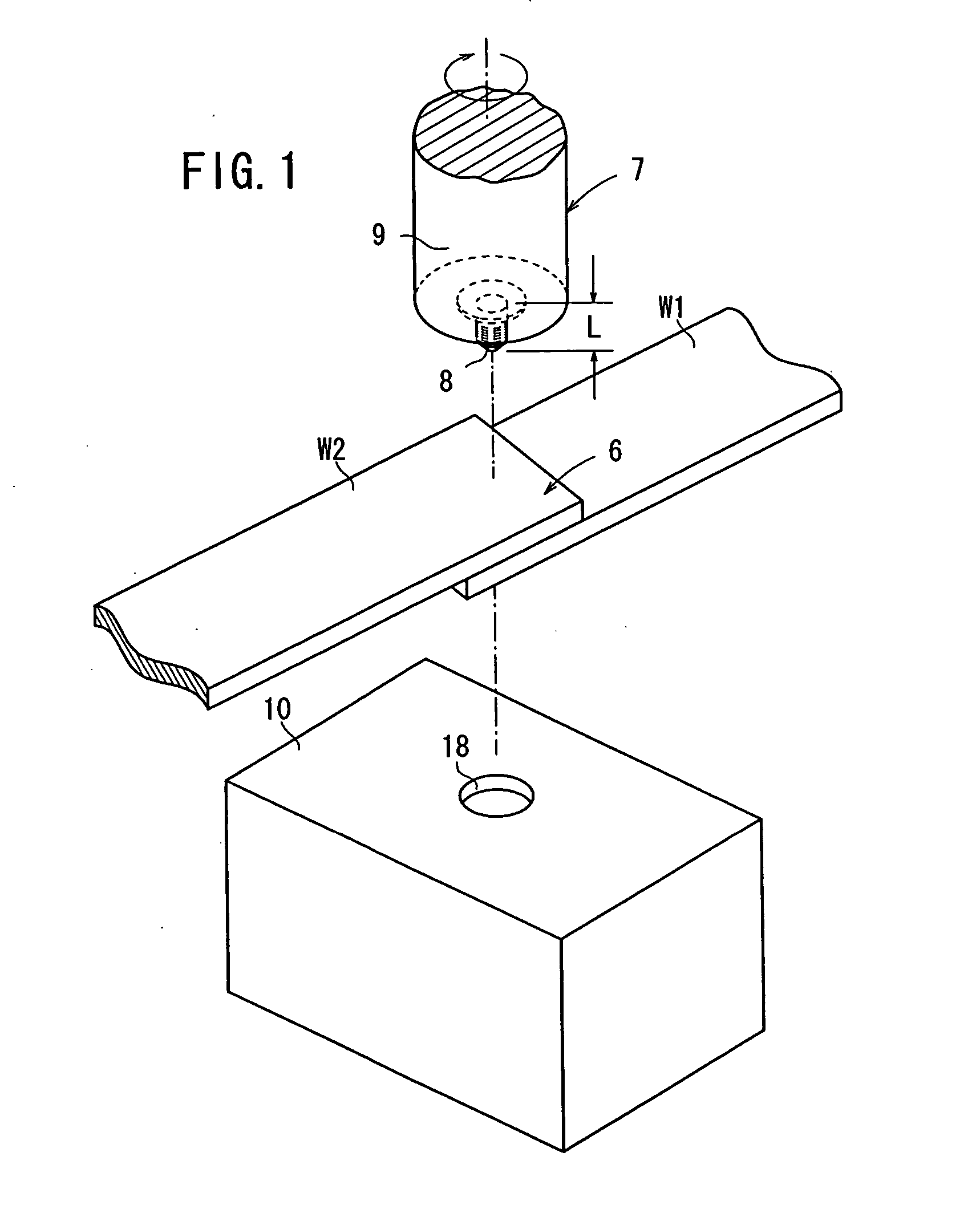
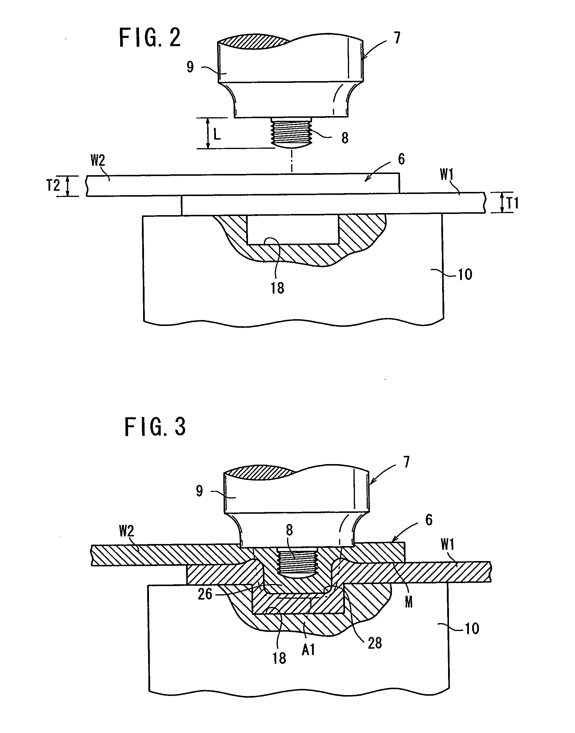
[0089]FIG. 1 is an enlarged fragmentary schematic perspective view of a support jig 10, a first workpiece W1 and a second workpiece W2 which are made of so-called 5000 aluminum denoted by 5000s according to JIS, and a friction stir welding tool 7, and FIG. 2 is an enlarged view, partly in vertical cross section, showing the manner in which a stacked assembly is placed on the support jig shown in FIG. 1. The support jig 10 is substantially in the shape of a rectangular parallelepiped, and has a recess 18 defined substantially centrally in an upper end face thereof. The recess 18 has a substantially hollow cylindrical shape having a substantially circular horizontal cross-section.

[0090] The first workpiece W1 and the second workpiece W2 are stacked one on the other, providing a stacked assembly 6. The stacked assembly 6 is friction-stir-welded in covering relation to the recess 18, as described later on.

[0091] The friction sti...

second embodiment

[0120] The friction stir welding method is performed as follows.

[0121] First, as shown in FIG. 12, the first workpiece W1 and the second workpiece W2 are stacked into the stacked assembly 6, which is placed on the upper end face of the placement block 122 of the placement jig 116. At this time, the stacked assembly 6 covers the recess 132.

[0122] Then, as shown in FIG. 14, the friction stir welding tool 7 (the probe 8) is placed with its axis L2 being aligned as much as possible with the axis L1 of the recess 132. At this time, it is not necessary to hold the axis L1 and the axis L2 in complete alignment with each other.

[0123] After the probe 8 is lowered to a position that is spaced a predetermined distance from the stacked assembly 6, the probe 8 is rotated in unison with the rotor 9. As shown in FIG. 13, the probe 8 is then brought into sliding contact with the upper end face of the stacked assembly 6. As the probe 8 is held in sliding contact with the upper end face of the sta...


PUM

PropertyMeasurementUnit
thickness T2aaaaaaaaaa

Abstract

A recess portion with a substantially circular cross-section is provided in the upper end surface of a supporting jig. When a probe of a device for friction stir welding is buried in the upper end surface of a layered portion, material in the vicinity of the buried portion flows plastically. This causes the plastically flowed material to flow into the recess portion, and as a result, the material is stirred in a relatively large region. When the material that flowed into the recess portion is cooled and solidified, a friction stir-welded portion-possessing member having a projection portion is obtained.

Description

TECHNICAL FIELD [0001] The present invention relates to a friction stir welding method for joining a stacked assembly of stacked members, a jig for use in such a friction stir welding method, a member with a friction-stir-welded joint produced by such a friction stir welding method, and a friction stir welding tool for joining a stacked or abutting assembly of metallic workpieces by friction stir welding. BACKGROUND ART [0002] Spot welding is generally relied upon to join a stacked assembly of members. In recent years, there has been proposed to join such a stacked assembly by friction stir welding (see, for example, Patent Documents 1 through 3). [0003]FIG. 28 shows a stacked assembly 6 comprising a first workpiece W1 and a second workpiece W2, which are stacked together, and placed on a support jig 3, and a friction stir welding tool 7 having a probe 8 embedded in the stacked assembly 6, in the same manner as with an apparatus shown in FIG. 1 of Patent Document 1. The reference ch...

Claims


Application Information

Patent Timeline
Patent Type & Authority Applications(United States)
IPC IPC(8): B23K20/12
CPCB23K20/1265B23K20/126
Inventor MURAKAWA, TOSHIHIROWAKISAKA, TAISEIOHKUBO, SATOSHI
Owner HONDA MOTOR CO LTD
Why Eureka
Try Eureka