Pin locking mechanism

a technology of locking mechanism and pin, which is applied in the direction of building types, ways, constructions, etc., can solve the problems of limiting the potential applications of this device and increasing the difficulty of adjustment, and achieve the effect of facilitating the rotation of the pin and ensuring the safety of the devi

Inactive Publication Date: 2006-10-19
BILBY MURRAY
View PDF10 Cites 10 Cited by
  • Summary
  • Abstract
  • Description
  • Claims
  • Application Information

AI Technical Summary

Benefits of technology

[0017] It is another object of the invention to provide a pin locking mechanism for rotatably secured nesting tubular members providing for easier rotation of the pin to permit or resist rotation of the nestin...

Problems solved by technology

The base must therefore be held in the desired position with respect to the frame during retightening of the screw, increasing the difficulty of adjustment...

Method used


Image

  • Pin locking mechanism
  • Pin locking mechanism
  • Pin locking mechanism

Examples


Embodiment Construction

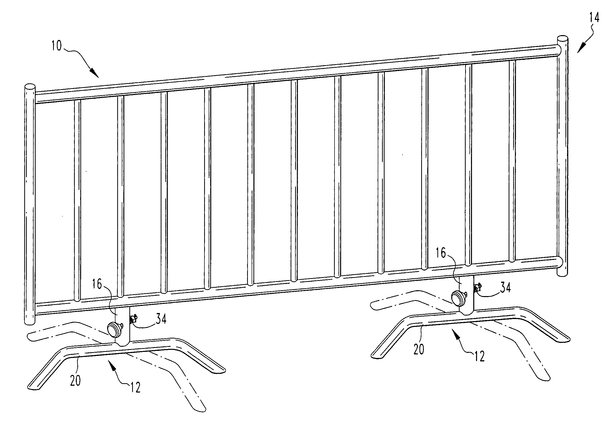
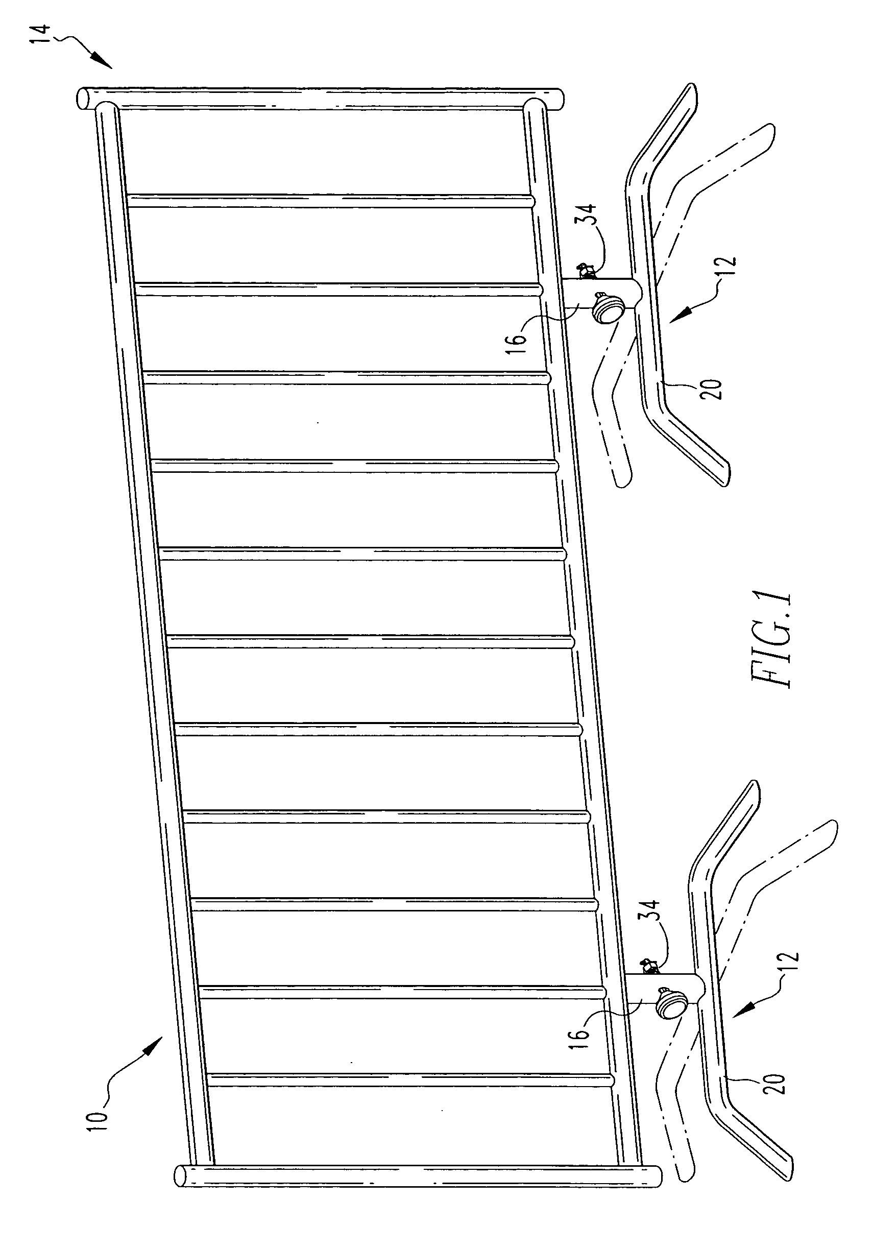
[0043] The present invention provides a pin locking mechanism for selectively permitting or resisting the rotation of a pair of nested tubular members with respect to each other. The pin locking mechanism is particularly useful for a crowd control barrier 10 having a pair of rotatably mounted bases 12 depending downward from a frame 14.

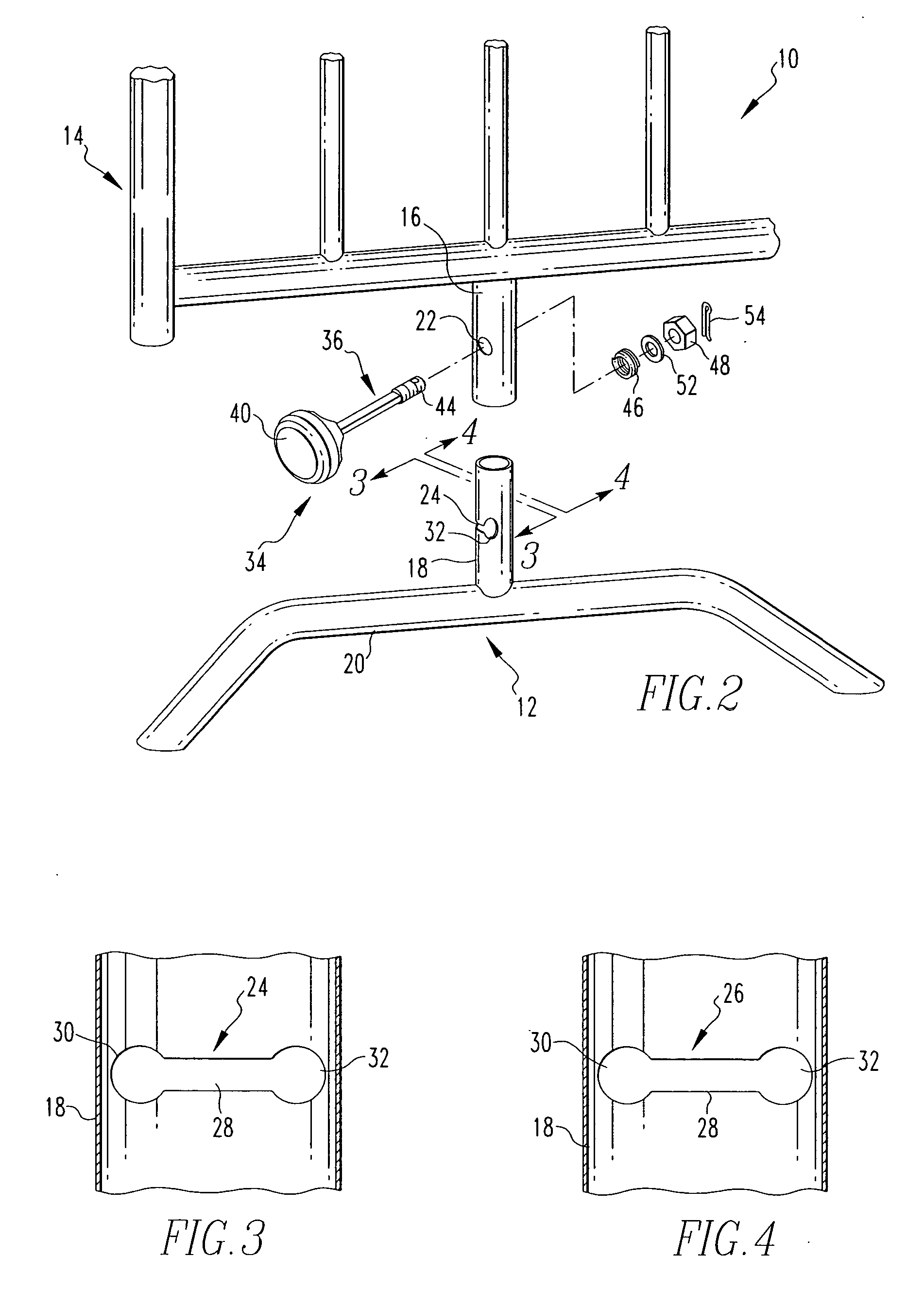
[0044] The components of the pin locking mechanism are best illustrated in FIGS. 2 to 7. Referring to FIG. 2, a pair of nested tubular members consisting of an outer tubular member 16 depending downward from the frame 14 and an inner tubular member 18 depending upward from the base 20. The outer tubular member 16 defines a pair of apertures 22 on opposing sides of the outer tubular member 16. The inner tubular member 18 defines a pair of opposing slots 24, 26 therein. Each of the slots 24, 26 defines a central portion 28 and a pair of end portions 30, 32. The end portions 30, 32 have a wider width than the central portion 28. In some preferred embodi...


PUM


Abstract

A pin locking mechanism selectively permits or resists the rotation of two nested tubular members with respect to each other. The pin has a substantially rectangular cross-section. The pin passes through a pair of holes defined in the outer tubular member, and a pair of slots defined within the inner tubular member. The slots have ends wider than their central portion, so that the pin may only fit within the central portion of the slot when it is substantially parallel to the slot, but may fit within the end portions when it is perpendicular to the slot. The nested tubular members may therefore be rotated with respect to each other when the pin is held substantially parallel with the slot, and rotation is resisted when the pin is held in a perpendicular orientation. A handle at one end of the pin is biased towards the outer tubular member by a spring at the opposite end of the pin. Rotation of the pin is resisted when the handle abuts the outer tubular member, and permitted when the handle is pulled away from the outer tubular member. The pin locking mechanism is particularly suitable for a pivoting base of a crowd control barrier.

Description

BACKGROUND OF THE INVENTION [0001] 1. Field of the Invention [0002] The present invention relates to a pin locking mechanism for selectively permitting and resisting the rotation of one tubular member with respect to a second tubular member nested therein. The invention is particularly suited to permitting the base of a crowd control barrier to be rotated so that the base is either substantially parallel to the barrier for stacking and shipment, or perpendicular to the barrier for use. [0003] 2. Description of the Related Art [0004] Selectively permitting and resisting rotation of one tubular member with respect to another nested tubular member is required for many purposes, for example, selectively resisting or permitting rotation of a base with respect to the frame of a crowd control barrier. Such bases should generally lie parallel to the barrier for storage or transportation to minimize the amount of space taken up by the barrier, and should lie perpendicular to the barrier duri...

Claims


Application Information

Patent Timeline
IPC IPC(8): E04H17/16
CPCE01F13/022
Inventor BILBY, MURRAY
Owner BILBY MURRAY
Why Eureka
Try Eureka