Optical pick-up and optical disk device

a technology of optical disk and optical pickup, which is applied in the manufacture of optical heads, data recording, instruments, etc., can solve the problems of actuator b>11/b> becoming out of control, unable to provide a normal error signal, and difficult to focus a laser light through the substrate of 0.6 mm to 1.2 mm thickness onto the information signal recording layer, etc., to achieve the effect of reducing the attachment of adhesives

Inactive Publication Date: 2006-10-19
CANON KK
View PDF7 Cites 12 Cited by
  • Summary
  • Abstract
  • Description
  • Claims
  • Application Information

AI Technical Summary

Problems solved by technology

However, an objective lens of a higher NA has a shorter focal length, requiring a shorter distance between the objective lens and the information signal recording layer, which makes it difficult to focus a laser light through the substrate of 0.6 mm to 1.2 mm thickness onto the information signal recording layer.
However, there are cases where a sudden shock or vibration, or contamination or a scratch on the optical disk 1 makes it impossible to provide a normal error signal, whereby the actuator 11 may become out of control.
At the time of such an abnormal operation, it is unavoidable that the movable part 16 is excessively displaced to come into contact with the optical disk 1.
In such a case, if the objective lens 20 and the optical disk 1 are brought into direct contact with each other, there are cases where either of the members is damaged and the recording / reproduction of a normal information signal may become impossible.
However, the above-mentioned official gazette does not disclose any assembly method of the objective lens holding system.
Therefore, the adhesive used for fixing the objective lens and protection member to the lens holding member may run out when applied even in a slightly excessive amount.
As a result, the adhesive may adhere to the disk-side surfaces of the objective lens and the protection member accidentally.
The adhesive adhering to the objective lens or protection member is generally not made of a material having a low hardness and slide resistance, unlike the protection member, so that collision between the adhesive adhering to the objective lens or protection member and the disk may damage the disk.

Method used


Image

  • Optical pick-up and optical disk device
  • Optical pick-up and optical disk device
  • Optical pick-up and optical disk device

Examples


example 1

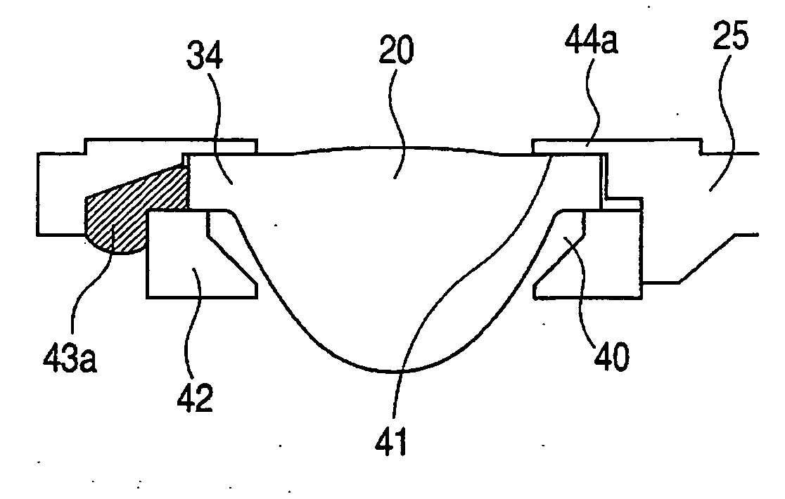
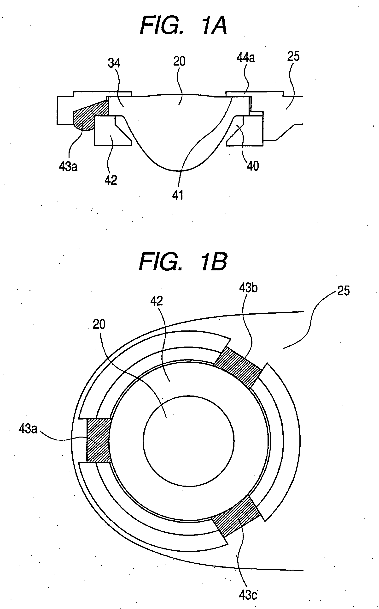
[0057]FIGS. 1A and 1B show an objective lens holding structure of Example 1. FIG. 1A is a longitudinal cross-sectional view, and FIG. 1B is a bottom view when viewed from below (i.e., showing a surface which does not face an optical disk).

[0058] A through hole 40 for disposing an objective lens 20 is formed in a lens holding member 25. In the hole 40, an annular aperture member 42 for restricting the diameter of a light flux, which is a member separate from the lens holding member 25, is fitted and provided together with the objective lens 20.

[0059] Furthermore, in the present example, a protection part 44a as protection means for the objective lens 20 is formed integrally with the lens holding member 25 so as to protrude above and inside the hole 40. Simultaneously, a lower surface of the portion of the protection part 44a protruding into the hole 40 constitutes an abutting surface 41 against the objective lens 20. A coating (or film) made of a material with flexibility and excel...

example 2

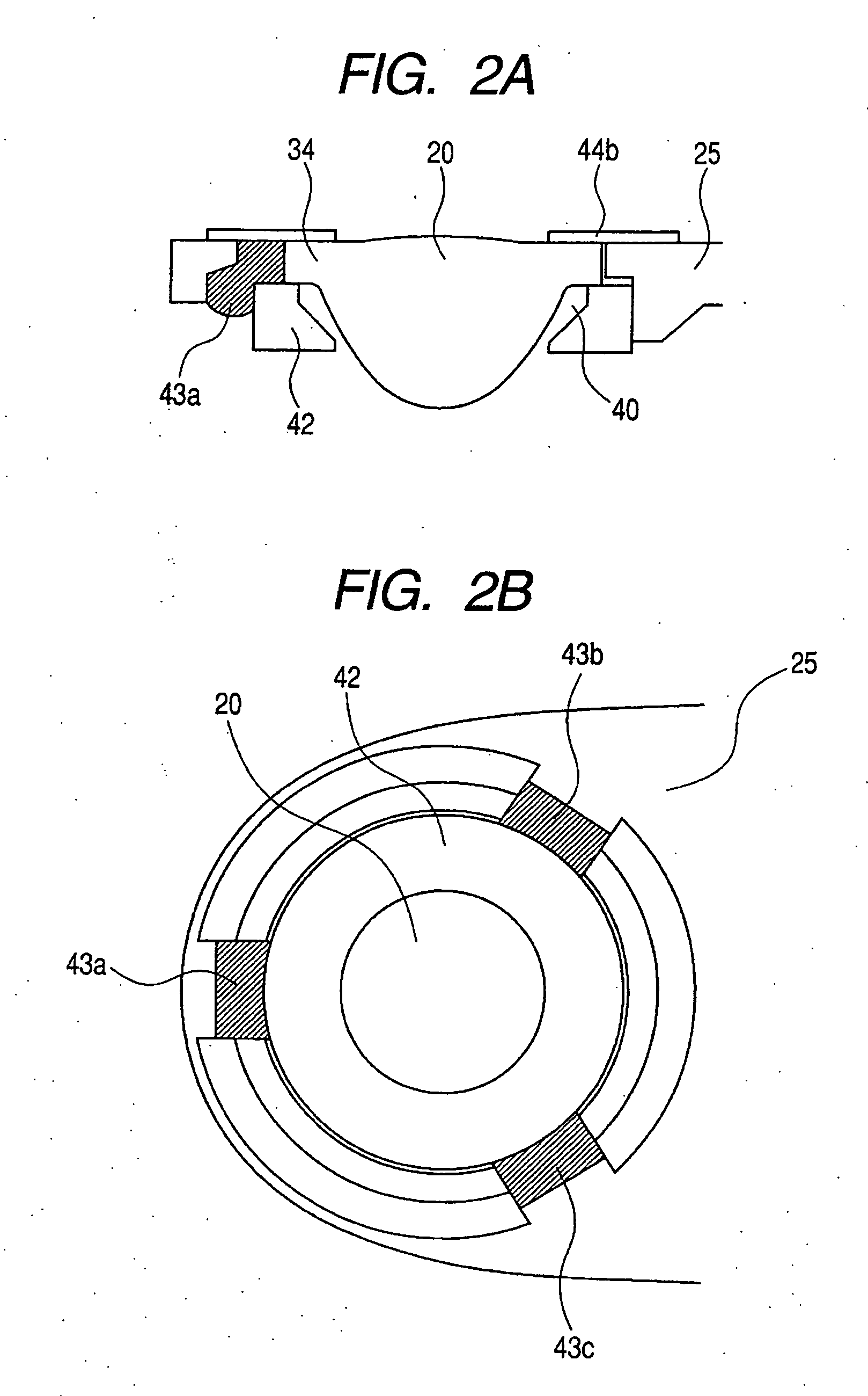
[0062]FIGS. 2A and 2B show an objective lens holding structure of Example 2. FIG. 2A is a longitudinal cross-sectional view, and FIG. 2B is a bottom view when viewed from below (i.e., showing a surface which does not face an optical disk).

[0063] A through hole 40 for disposing an objective lens 20 is formed in a lens holding member 25. In the hole 40, an annular aperture member 42 for restricting the diameter of a light flux, which is a member separate from the lens holding member 25, is fitted and provided together with the objective lens 20.

[0064] Furthermore, in the present example, an annular protection member 44b as protection means for the objective lens 20 is bonded to the upper surfaces of the lens holding member 25 and the objective lens 20. FIG. 4 is a cross-sectional view showing the configuration of the protection member 44b. The protection member 44b is a sheet of a uniform thickness in which a coating 46 made of a material with flexibility and excellent slidability i...

example 3

[0070]FIGS. 3A and 3B show an objective lens holding structure of Example 3. FIG. 3A is a longitudinal cross-sectional view, and FIG. 3B is a bottom view when viewed from below (i.e., showing a surface which does not face an optical disk).

[0071] A through hole 40 for disposing an objective lens 20 is formed in a lens holding member 25. In the hole 40, an annular aperture member 42 for restricting the diameter of a light flux, which is a member separate from the lens holding member 25, is fitted and provided together with the objective lens 20.

[0072] As with Example 2, also in the present example, an annular protection member 44b as protection means for the objective lens 20 is provided on the upper surface of the lens holding member 25. The protection member 44b consists of a thin plate of a metal material, and a downwardly bent portion is formed in a part thereof. Further, a coating 46 made of a material with flexibility and excellent slidability is formed on its upper surface, a...


PUM

PropertyMeasurementUnit
thicknessaaaaaaaaaa
thicknessaaaaaaaaaa
thicknessaaaaaaaaaa

Abstract

In order to reduce attachment of an adhesive to a disk-side surface of a protection member or an objective lens during an adhesion step, there is provided an optical pick-up, which includes an objective lens for collecting / irradiating a laser light to an optical disk, and an objective lens holding member for holding the objective lens, wherein a plurality of cutout portions for injecting therein an adhesive for fixing the objective lens are provided in a side of the objective lens holding member opposite to a side thereof facing the optical disk.

Description

BACKGROUND OF THE INVENTION [0001] 1. Field of the Invention [0002] The present invention relates to an optical pick-up having an objective lens for collecting a laser light to an optical disk, and an optical disk device which collects a laser light on an information signal recording layer provided in an optical disk using the optical pick-up to perform recording / reproduction of an information signal. [0003] 2. Related Background Art [0004] Hitherto, there has been put to practical use an optical disk device which collects a laser light into a fine light spot of an information signal recording layer of an optical disk by using an optical pick-up with an objective lens to thereby record an information signal or reproduces a recorded information signal from a reflected light thereof. Then, in recent years, in such an optical disk device, it has become possible to raise the NA to 0.8 or more by improvement in design and manufacturing technique of an objective lens. By using such an obj...

Claims


Application Information

Patent Timeline
Patent Type & Authority Applications(United States)
IPC IPC(8): G11B7/135
CPCG11B7/121G11B7/22G11B7/1374
Inventor ISHII, KAZUYOSHI
Owner CANON KK
Why Eureka
Try Eureka