Mechanically isolated wireless communications system and method

a wireless communication system and mechanical isolation technology, applied in the direction of substation equipment, electrical equipment, support structure mounting, etc., can solve the problems of increasing overall system complexity and weight, and adding up to significant weigh

Active Publication Date: 2006-10-19
THE BOEING CO
View PDF4 Cites 68 Cited by
  • Summary
  • Abstract
  • Description
  • Claims
  • Application Information

AI Technical Summary

Benefits of technology

[0004] The present invention is directed to an apparatus and method for channeling wireless energy between a plurality of independent components to enable communication between the components. In one preferred embodiment an equipment bay is utilized for supporting a plurality of independent components adjacent one another. The plenum or backplane may form a cooling channel for also circulating a cooling air flow through the equipment bay. The equipment bay includes a plenum or a backplane area adjacent the components. The equipment bay, in one preferred form, may be formed from a material that impedes the transmission of electromagnetic wave energy, thus isolating the plenum or backplane area

Problems solved by technology

However, this involves complex integration and wiring assemblies that increase overall system complexity and weight.
In applications involving mobile platforms, the additional wi

Method used


Image

  • Mechanically isolated wireless communications system and method
  • Mechanically isolated wireless communications system and method
  • Mechanically isolated wireless communications system and method

Examples


Embodiment Construction

[0015] The following description of the preferred embodiment(s) is merely exemplary in nature and is in no way intended to limit the invention, its application, or uses.

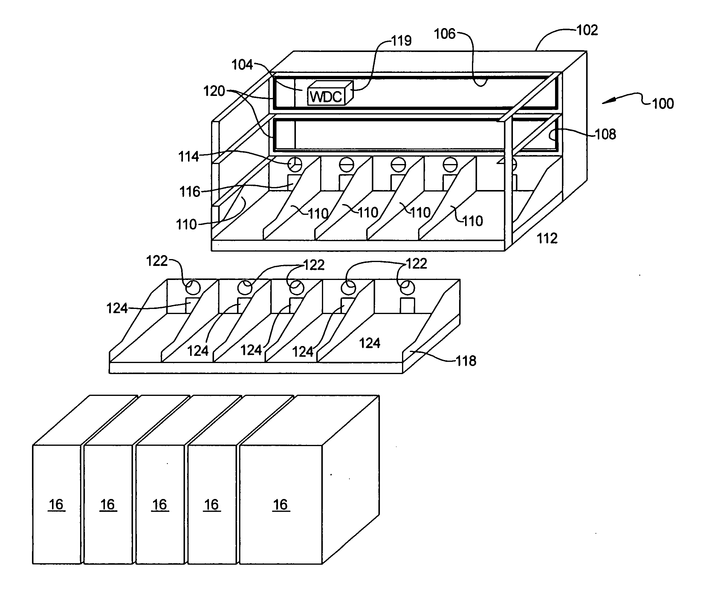
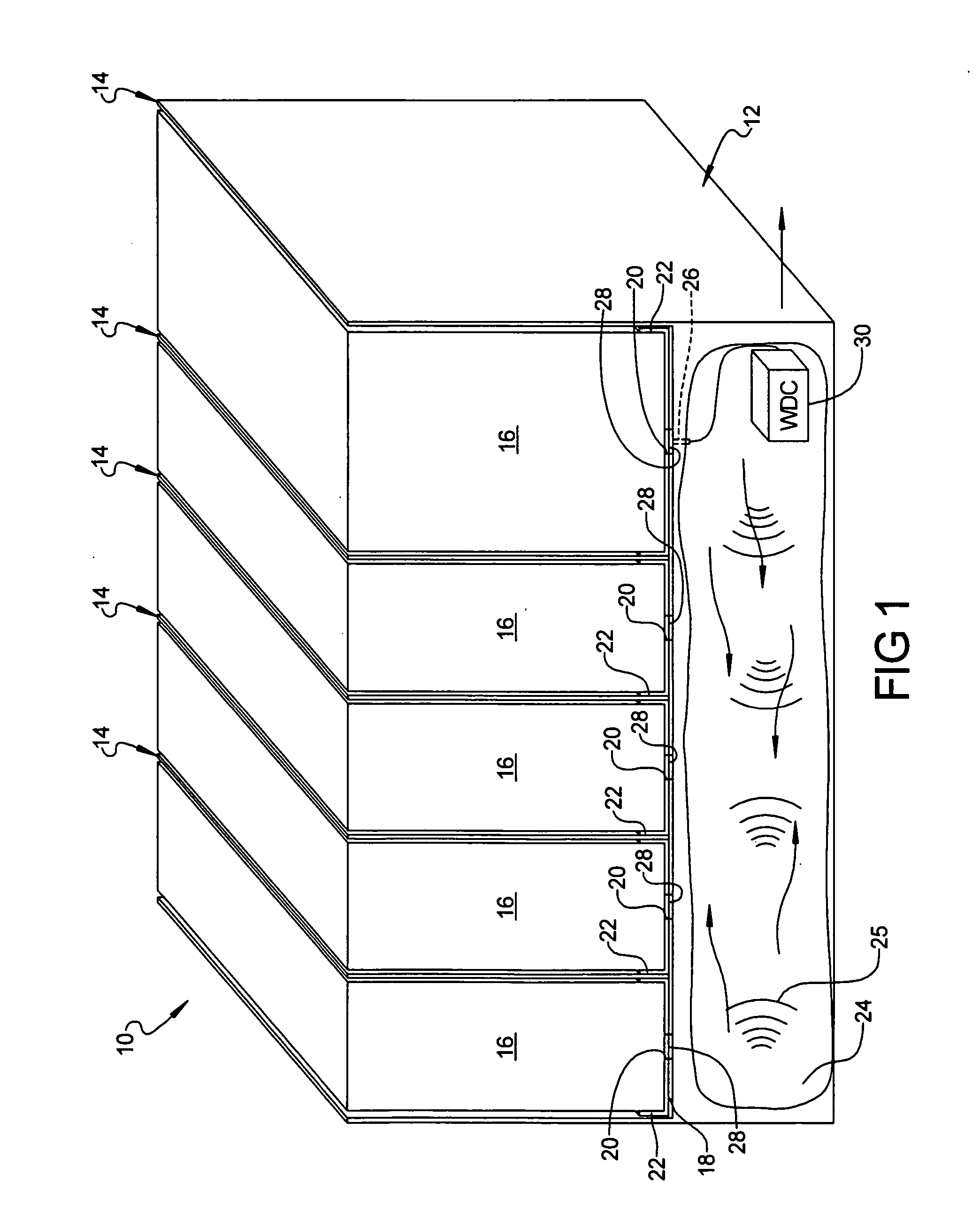
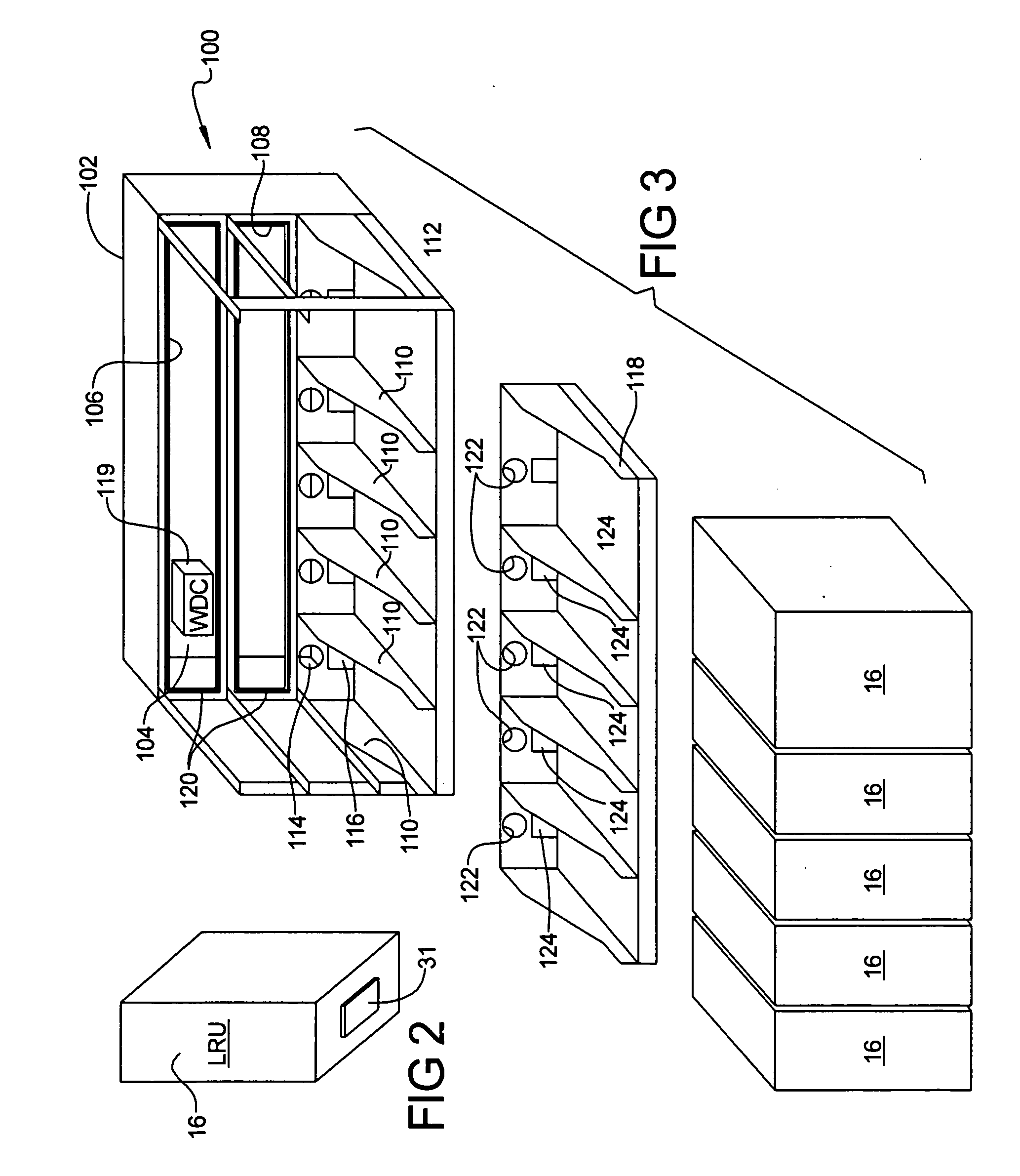
[0016] Referring to FIG. 1, there is shown an equipment shelf 10 in accordance with a preferred embodiment of the present invention. The equipment shelf 10 includes a housing 12 forming a plurality of trays or slots 14 for accepting and supporting a corresponding plurality of line replaceable units (LRUs) 16. The housing 12 is preferably made from metal, and more preferably from aluminum, to act as an electromagnetic wave isolator to shield the LRUs from electromagnetic wave energy or optical energy present in the vicinity of the equipment tray 10.

[0017] The equipment tray 10 also includes a wall portion 18 having a plurality of openings 20. One or more RF mesh gaskets 22 may be included to form a seal around each opening 20 to further ensure that stray electromagnetic wave energy does not radiate into the housing ...


PUM


Abstract

A system and method for transmitting wireless energy between two or more components housed within a faraday-like cage structure. In one preferred form a cooling plenum of an equipment rack supporting a plurality of independent components is used for transmitting wireless signals between the components. In another form a wireless backplane is formed in an equipment rack that houses a plurality of LRUs. In another example a card file housing a plurality of components forms a faraday-like cage for enabling transmission of wireless signals, either electromagnetic wave or optical signals, between various circuit boards held within the card file. The various preferred embodiments eliminate the need for expensive, bulky and heavy electrical or optical cabling to be used to intercouple the components supported within the support structure for communication.

Description

FIELD OF THE INVENTION [0001] The present invention relates to wireless communications systems, and more particularly to a system and method for implementing wireless communications channels within an electronic equipment bay or other form of support structure. BACKGROUND OF THE INVENTION [0002] Many electronic systems, and particularly commercial aircraft avionics systems, require a highly reliable system interface that can support a plurality of electronic components, such as line replaceable units (LRUs), in a common equipment rack or shelf within an electronics equipment bay. However, this involves complex integration and wiring assemblies that increase overall system complexity and weight. In applications involving mobile platforms, the additional wiring, typically in the forms of wiring harnesses, connectors, etc., necessary to integrate a number of LRUs for communication with one another, can add up to significant weight. However, with many mobile platforms, and especially mi...

Claims


Application Information

Patent Timeline
IPC IPC(8): H04M1/00
CPCH05K7/1412
Inventor LEE, DONALD B.MITCHELL, BRADLEY J.SCHULTZ, LARRY R.
Owner THE BOEING CO
Why Eureka
Try Eureka