Pacemaker lead with motion sensor
- Summary
- Abstract
- Description
- Claims
- Application Information
AI Technical Summary
Benefits of technology
Problems solved by technology
Method used
Image

Examples
Embodiment Construction
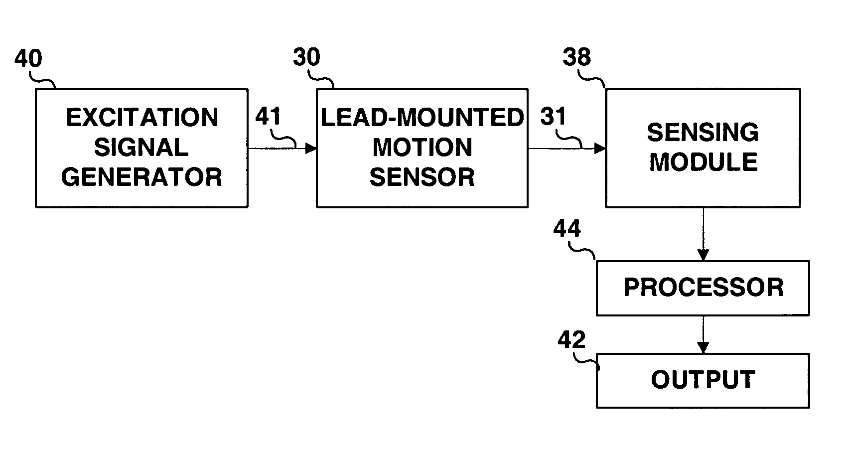
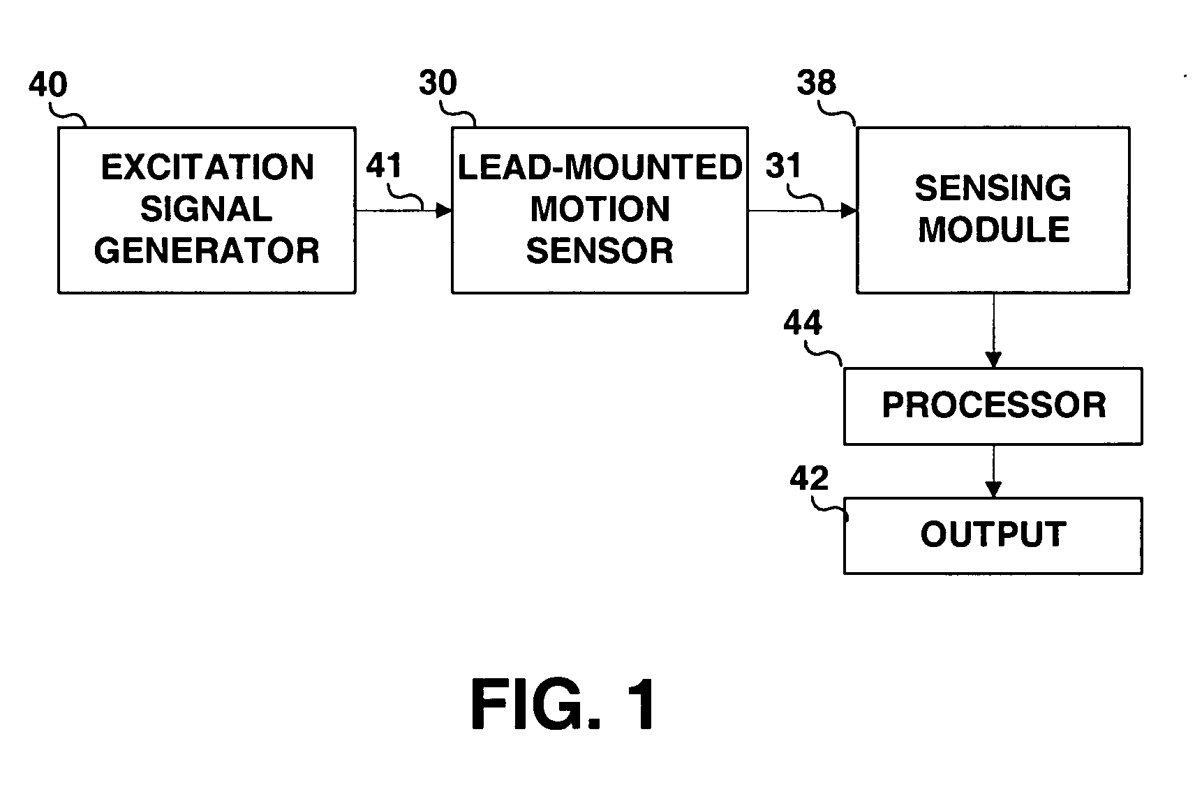
[0020]FIG. 1 is a simplified block diagram providing an overview of a cardiac wall motion sensing system provided in accordance with the invention. Generally, the system includes a lead mounted motion sensor 30 that is responsive to an excitation signal produced by excitation signal generator 40. As will be described herein, the system may be embodied as a magnetic or electromagnetic system wherein excitation signal generator 40 produces an (electro)magnetic field that induces a current in motion sensor 30, which is embodied as a receiver coil mounted at or near the distal end of a cardiac lead. The system may alternatively be an electronic system wherein excitation signal generator 40 produces radio-frequency (RF) signal that causes motion sensor 30, which can be embodied as an electronic circuit with an antenna or resonance strip, to resonate. Alternatively motion sensor 30 can be embodied as an electrode used for measuring an induced voltage signal in response to an externally ap...
PUM
 Abstract
Description
Claims
Application Information
 - R&D
- Intellectual Property
- Life Sciences
- Materials
- Tech Scout
- Unparalleled Data Quality
- Higher Quality Content
- 60% Fewer Hallucinations
Browse by: Latest US Patents, China's latest patents, Technical Efficacy Thesaurus, Application Domain, Technology Topic, Popular Technical Reports.
© 2025 PatSnap. All rights reserved.Legal|Privacy policy|Modern Slavery Act Transparency Statement|Sitemap|About US| Contact US: help@patsnap.com