Functional shoe

a functional and shoe technology, applied in the field of shoes, can solve the problems of poor health, little electricity applied, and difficult to achieve the effect of stimulating the nerve points of the sole, promoting blood circulation, and promoting health

Inactive Publication Date: 2006-10-19
G MAN
View PDF9 Cites 34 Cited by
  • Summary
  • Abstract
  • Description
  • Claims
  • Application Information

AI Technical Summary

Benefits of technology

[0062] As described above, according to the present invention, a physical stimulus, a magnetic force, and a micro current act together through acupressure parts provided on a sole of a shoe, thus stimulating nerve points of the sole, therefore promoting blood circulation, and affecting organs in the body to promote the health.
[0063] Further, according to the present invention, a shoe is provided with a b

Problems solved by technology

However, the prior art is problematic in that little electricity is applied.
However, the current generated in a conventional piezoelectric sensor is very weak, that is, about several pico-amperes (pA).
Thus, the prior art is problematic in that little generated micro current is transmitted through the surface of the sole to the interior thereof.
Further, the prior art is problematic in that there is little effect, even though the current is transmitted to the sole.
Due to these problems, the aforementioned construction is impractical, so that it is seldom used.
However, since the shoe has the following problems, it is useless in actual life.
Such a structure does not consider recovering power when walking, so that much power is consumed.
Thereby, a power changing or charging operation is frequently required, thus inconveniencing a user.
Hence, it is difficult to use the shoe in actual life.
Second, the shoe comprise

Method used


Image

  • Functional shoe
  • Functional shoe
  • Functional shoe

Examples


first embodiment

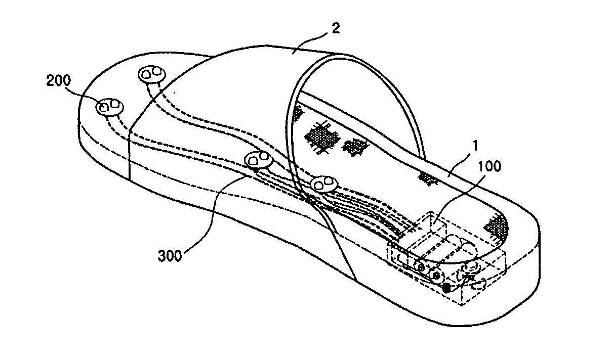
[0245] As shown in FIG. 22, according to this embodiment, a micro-current generating part 100 comprises a piezoelectric actuator, and is installed in an outsole 1 of a shoe.

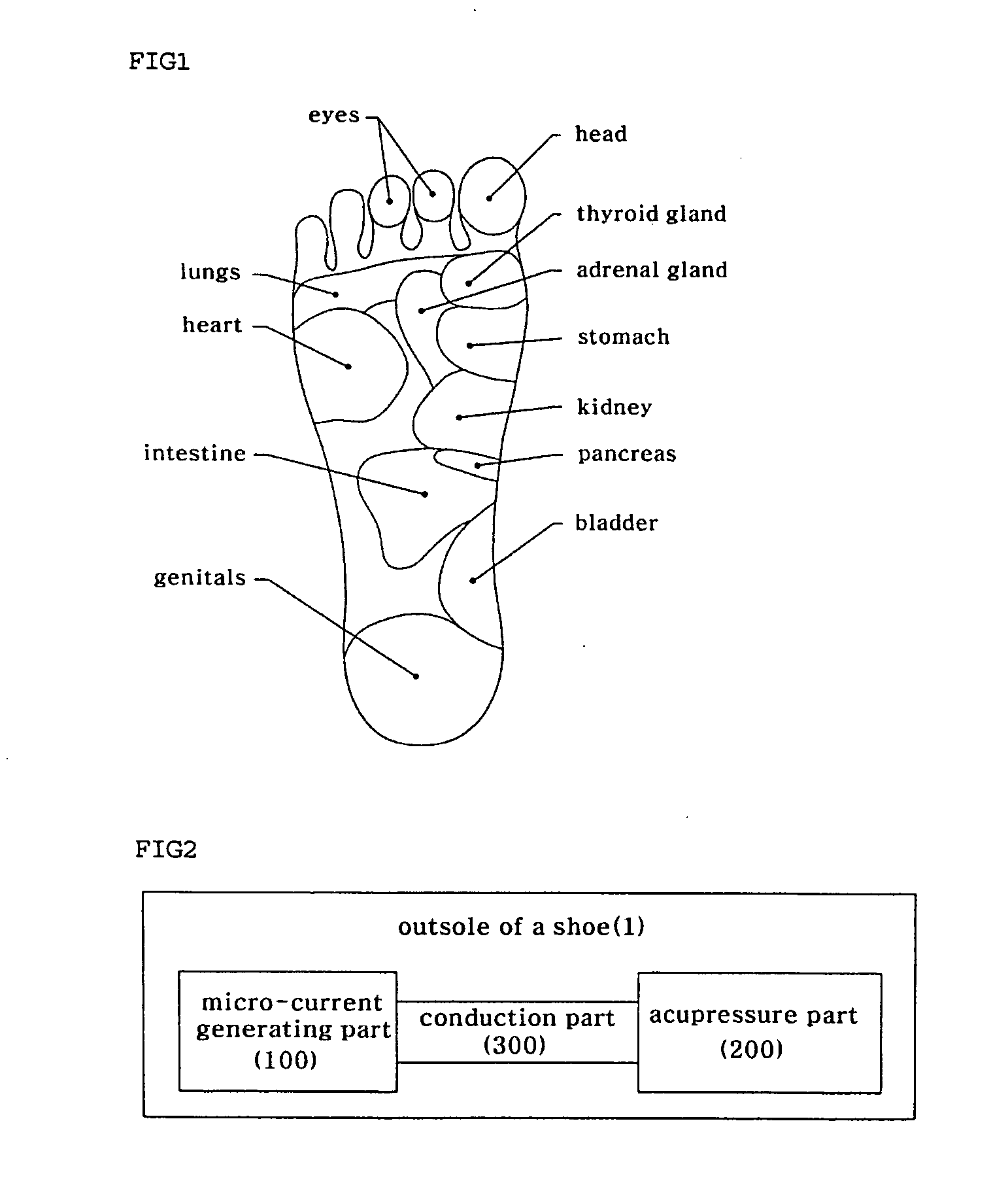
[0246] That is, the micro-current generating part 100, an acupressure part 200, and a conduction part 300 are installed in the outsole 1. Such a construction is applicable to all kinds of shoes.

[0247] Thus, a shoe having the functional parts in the outsole 1 will be described below.

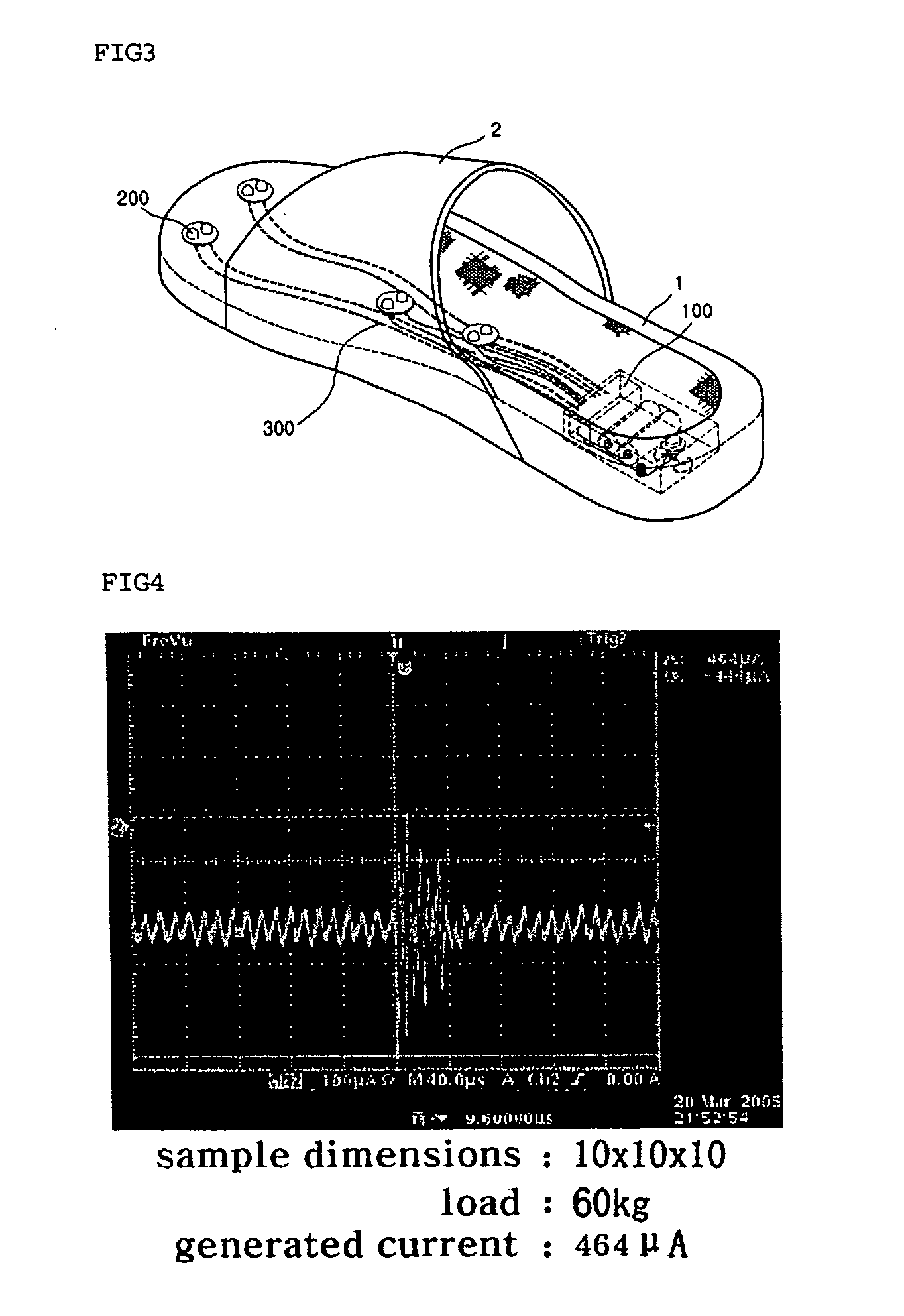
[0248] In the construction of the outsole 1, the micro-current generating part 100 is positioned in the heel portion of the outsole 1. The position is the position on the shoe where the highest pressure is applied.

[0249] Further, the heel portion of the shoe has the largest space, so that it is easy to install the micro-current generating part 100. The heel portion is a position which is capable of using force transmitted from the sole.

[0250] That is, according to this embodiment, pressure applied by the heel when walking is used ...

second embodiment

[0288] As shown in FIG. 24, according to this embodiment, an acupressure part 200 is provided in an inner sole of a shoe, and the acupressure part 200 itself has a piezoelectric actuator.

[0289] That is, the piezoelectric actuator which is the micro-current generating part 100, is embedded under each acupressure part 210, 220. By the sole pressure transmitted through the acupressure parts 210 and 220, each piezoelectric actuator is driven.

[0290] To this end, the acupressure parts 210 and 220 are installed in portions where the nerve points of the sole connected to the organs in the body are located, as in the first embodiment.

[0291] Further, each acupressure part 210, 220 is made of a conductive material. Preferably, the acupressure part 210, 220 is made of a magnet having magnetism.

[0292] The piezoelectric actuator is embedded under each acupressure part 210, 220, and the piezoelectric actuator directly acts on respective nerve points. Thus, the size of the piezoelectric actuato...

third embodiment

[0295] As shown in FIG. 18, according to this embodiment, a micro-current generating part 100 includes a battery 110, a micro-current generating circuit 120, and a switch unit 130. The micro-current generating part 100 is provided in a shoe sole 1, and so is applicable to all kinds of shoes.

[0296] That is, according to this embodiment, as a switch applying micro current, the load applied by the sole when walking is used as a contact point of the switch unit.

[0297] Further, the battery 110 and the micro-current generating circuit 120 are housed in an outer case 100a which is made of a synthetic resin material to have high strength, so that the damage to the battery 110 and the micro-current generating circuit 120 due to repeated impact loads is prevented.

[0298] Further, a manual switch 134 which controls the supply of power from the battery 110 is embedded in an upper 2 and connected to a lead wire 134a.

[0299] That is, the manual switch 134 is installed on the upper 2 of the shoe...


PUM


Abstract

Disclosed herein is a functional shoe, capable of applying micro current to the sole. The shoe includes a micro-current generating part, an acupressure part, and a conduction part. The micro-current generating part is inserted in a side of the shoe, thus generating predetermined micro current and voltage. The acupressure part is made of a conductive material, and is provided on a portion where nerve points of a sole connected to organs in a body are located, thus simultaneously performing physical acupressure action and conduction of micro current. The conduction part is connected between the micro-current generating part and the acupressure part, thus transmitting the generated micro current and voltage to the acupressure part. Thereby, the functional shoe simultaneously performs physical acupressure action on specific nerve points of the sole, and transmits micro current to the nerve points using external force applied when walking.

Description

CROSS-REFERENCE TO RELATED APPLICATIONS [0001] Applicants claim priority benefits under 35 U.S.C. § 119(e) of Korean Patent Application No. 10-2005-0030874 filed Apr. 14, 2005 and Korean Patent Application No. 10-2005-0119565 filed Dec. 8, 2005. FIELD OF THE INVENTION [0002] The present invention relates, in general, to shoes and, more particularly, to a functional shoe, in which a micro current having a predetermined magnitude is supplied so as to stimulate a human body through the sole when walking, thus providing a physical therapy function. BACKGROUND OF THE INVENTION [0003] Recently, due to a rise in the standard of living and various desires of consumers, various kinds of shoes having a variety of designs have been manufactured. Further, various special shoes having various functions have come onto the market. [0004] At first, shoes served as means simply for protecting the feet. However, the shoes have been developed so as to be one device having various functions. [0005] Tha...

Claims


Application Information

Patent Timeline
IPC IPC(8): A61B17/00A43B3/35
CPCA43B1/0054A43B3/0005A43B7/00A61H2205/125A61H39/002A61H39/04A43B7/146A43B3/34
Inventor KOO, SUNG JINCHO, SUNG LAEMOON, JIN BOK
Owner G MAN
Why Eureka
Try Eureka