
Pathway information display device

a display device and path information technology, applied in the field of path information display devices, can solve the problems of difficult to distinguish between edges and labels, and achieve the effects of optimizing calculated energy, reducing labor intensity, and reducing labor intensity

Inactive Publication Date: 2006-10-19
CELESTAR LEXICO SCI
View PDF1 Cites 29 Cited by
  • Summary
  • Abstract
  • Description
  • Claims
  • Application Information

AI Technical Summary

Benefits of technology

[0020] According to the apparatus, the method, and the program, a binary relation model of pathway information configured by nodes and edges is created. The pathway information includes information on genetic control pathways, metabolic pathways, signal-transfer pathways or the like. By mapping main information on a binary relation, the complicated pathway information can be simplified into a model and integrally expressed. Furthermore, a repulsive force generated between the nodes within a certain distance is calculated, and an attractive force generated between the nodes connected to each other by the edges is calculated. A coordinate position of each node is determined based on the repulsive force and the attractive force, and the nodes and the edges are drawn in the form of a graph. By doing so, even if the pathway information is medium or large-sized pathway information or complicated pathway information, a graph that is readable to some extent can be automatically drawn within a certain time. If the layout is executed only by forces based on the repulsive force and the attractive force between each node pair, the nodes are often so close to each other to thereby make the edges and their labels difficult to distinguish from one another. According to the present invention, therefore, the repulsion field is set for a preset peripheral region of the nodes so as to prevent every node pair from being too close to each other. That is, according to the invention, the repulsion field is set for the preset peripheral region of the nodes and the repulsive force and the attractive force are then calculated. Based on the calculated repulsive force and attractive force, and the repulsive force and attractive force in the repulsion field, the coordinate position of each node is determined by the spring layout system, the nodes and the edges are drawn in the form of a graph, and the pathway information is displayed as a graph using the binary relation model. Therefore, overlapping of the nodes and the edges themselves and their labels is avoided, thereby further improving readability of the graph.
[0046] According to the recording medium, by causing a computer to read the program recorded in the recording medium and execute the program, the program can be realized using the computer. The same advantages as those of the respective methods can be obtained.

Problems solved by technology

If the layout is executed only by forces based on the repulsive force and the attractive force between each node pair, the nodes are often so close to each other to thereby make the edges and their labels difficult to distinguish from one another.

Method used


Image

  • Pathway information display device
  • Pathway information display device
  • Pathway information display device

Examples


Embodiment Construction

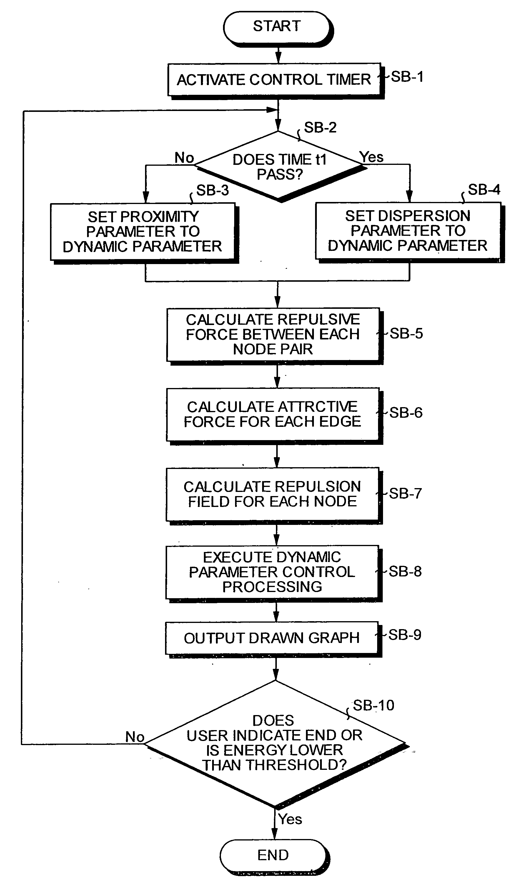
[0068] (I) Embodiments of a pathway information display apparatus, a pathway information display method, a program, and a recording medium according to the present invention will be explained below in detail with reference to the accompanying drawings. Note that the invention is not limited by the embodiments.

[0069] In the following embodiments, an instance that the present invention is applied to a bioinformatics system that draws a graph of pathway information such as a genetic control pathway, a metabolic pathway or a signal-transfer pathway will be explained. However, the invention is not limited to the instance, and can be similarly applied to a system that draws a graph of pathway information in every field.

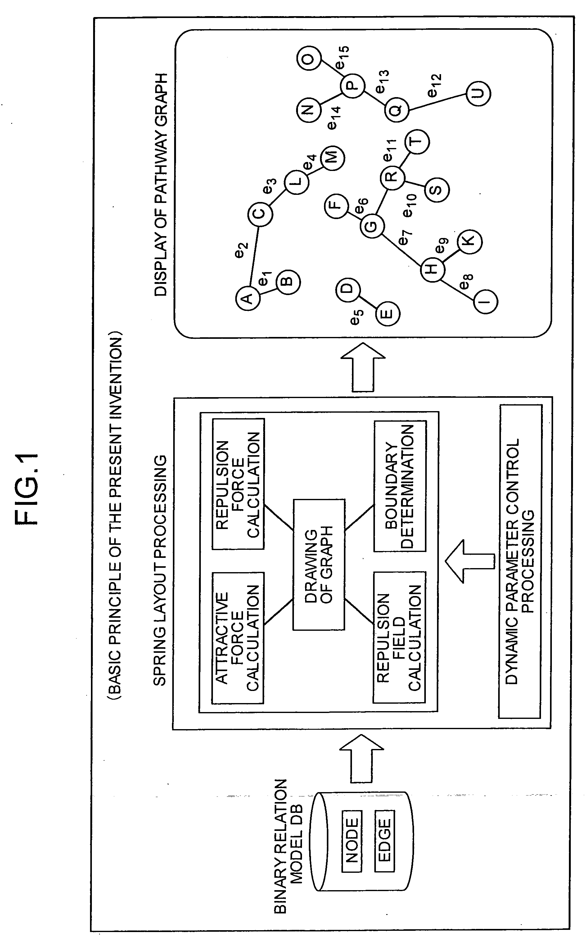
[Outline of the Present Invention]

[0070] The outline of the basic principle of the present invention will be explained first, and a configuration, processing and the like of the invention will be explained next in detail. FIG. 1 is a conceptual view of the outline of the...


PUM


Abstract

A spring layout system or the like is then executed to nodes (A to U in FIG. 10) and edges (e1 to e15) defined in a binary relation model database to thereby automatically draw a graph. Nodes are replaced by rings and edges are replaced by springs, and a layout is calculated so that forces of the springs (a repulsive force and an attractive force) acting on the rings can realize a minimum energy state of the system. Node coordinate positions are determined based on the calculated forces, and the nodes and the edges are drawn in the form of a graph. The “repulsive force” is a force generated between every pair of nodes present within a certain distance, and the nodes are dispersed and overlaps of nodes are removed by the repulsive force. The “attractive force” is a force generated between every pair of nodes present within the certain distance. The nodes connected to each other by edges by the attractive force are closer to each other. Therefore, relevant nodes can be made closer and easily discriminated from irrelevant nodes.

Description

TECHNICAL FIELD [0001] The present invention relates to a pathway information display apparatus, a pathway information display method, a program, and a recording medium. More specifically, the invention relates to a pathway information display apparatus, a pathway information display method, a program, and a recording medium for automatically drawing a binary relation model. [0002] The present invention also relates to a directed graph layout apparatus, a directed graph layout method, a program, and a recording medium. More specifically, the invention relates to a directed graph layout apparatus, a directed graph layout method, a program, and a recording medium capable of expressing flows of edges of a directed graph. BACKGROUND ART (I) Techniques for creating a model of a metabolic circuit, a signal-transfer pathway, or a genetic control pathway in the form of a graph have been conventionally proposed in the bioinformatics field. [0003] For example, P. Karp and S. M. Paley, “Autom...

Claims


Application Information

Patent Timeline
IPC IPC(8): G06F17/10G06F17/30G06T11/20G16B5/10G16B5/30
CPCG06T11/206G16B5/00G16B45/00G16B5/30G16B5/10
Inventor NITTA, KIYOSHISUZUKI, ICHIRO
Owner CELESTAR LEXICO SCI
Learn More