Filter cartridge cleaning apparatus

Inactive Publication Date: 2006-10-26
GAU JI DING
View PDF7 Cites 9 Cited by
  • Summary
  • Abstract
  • Description
  • Claims
  • Application Information

AI Technical Summary

Benefits of technology

[0005] An objective of the present invention is to provide a cleaning apparatus for

Problems solved by technology

Current cleaning operation for cleaning the filter cartridges is manually carried out one by one, which is time-consuming, and the result is unsatisfactory.
Lost occurs due to shutd

Method used


Image

  • Filter cartridge cleaning apparatus
  • Filter cartridge cleaning apparatus
  • Filter cartridge cleaning apparatus

Examples


Embodiment Construction

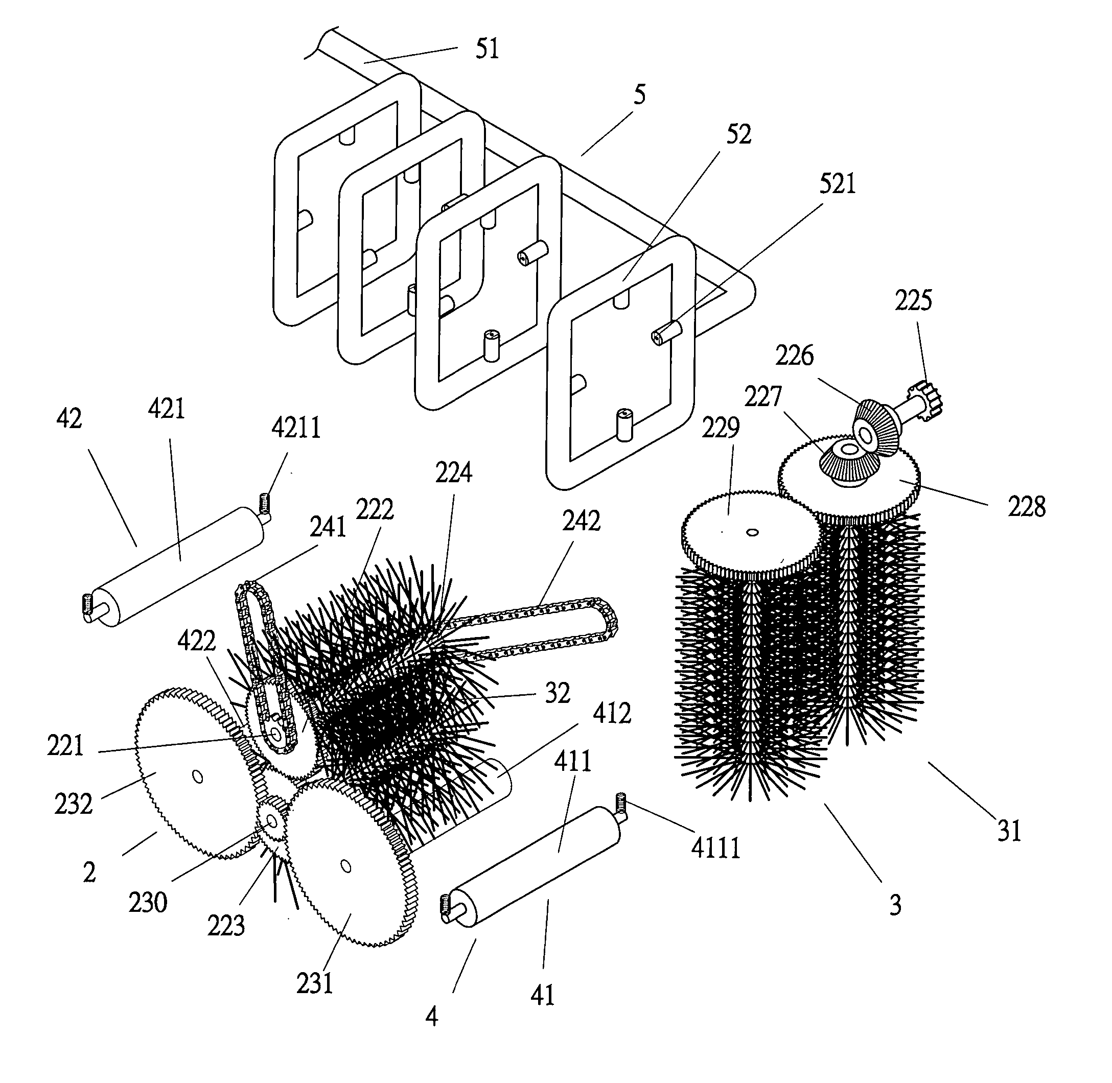
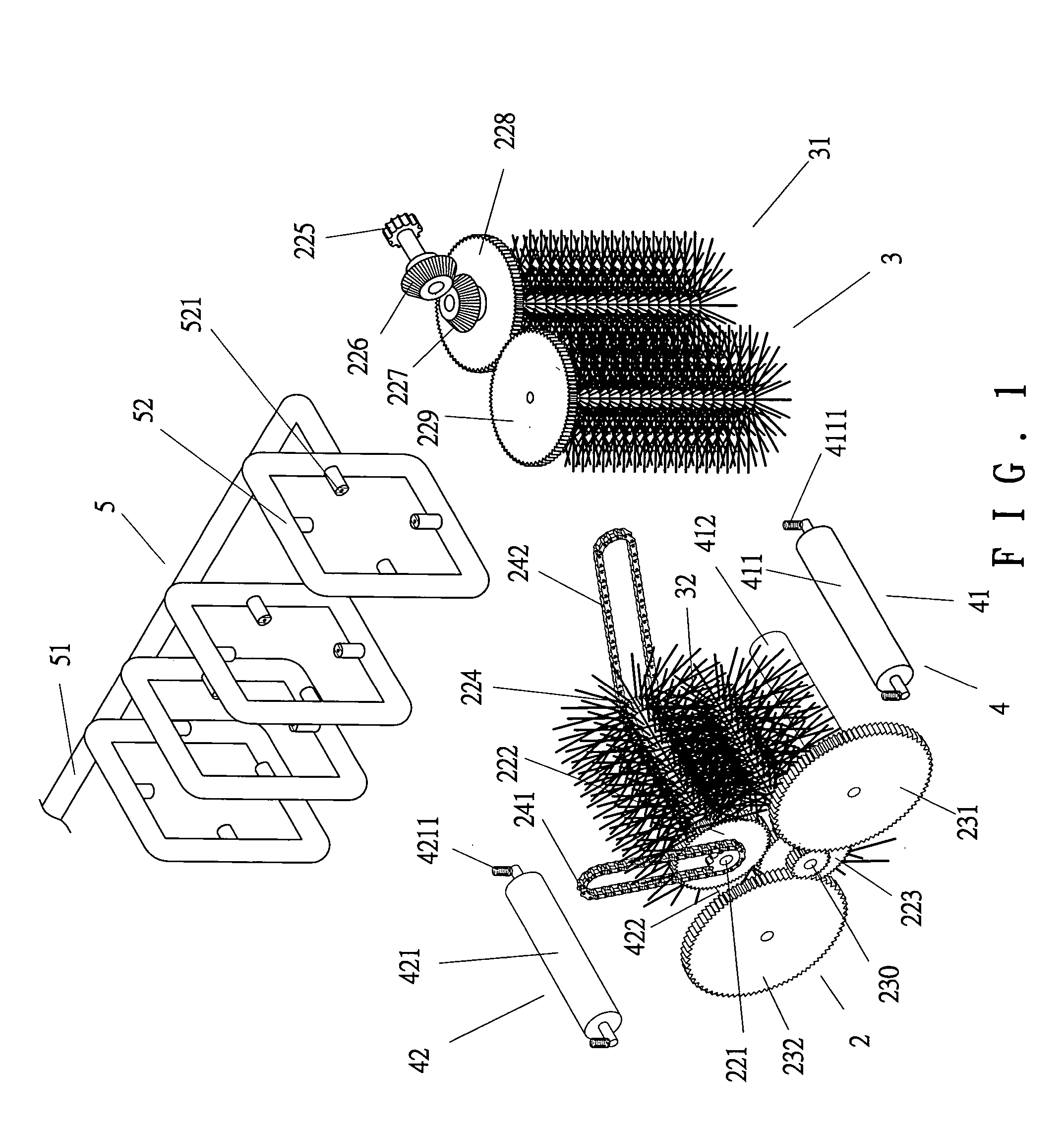
[0026] Referring to FIGS. 1 through 5, a filter cartridge cleaning apparatus 10 in accordance with the present invention comprises a housing 1, a transmission mechanism 2, a brush mechanism 3, a guiding mechanism 4, and a water supply mechanism 5.

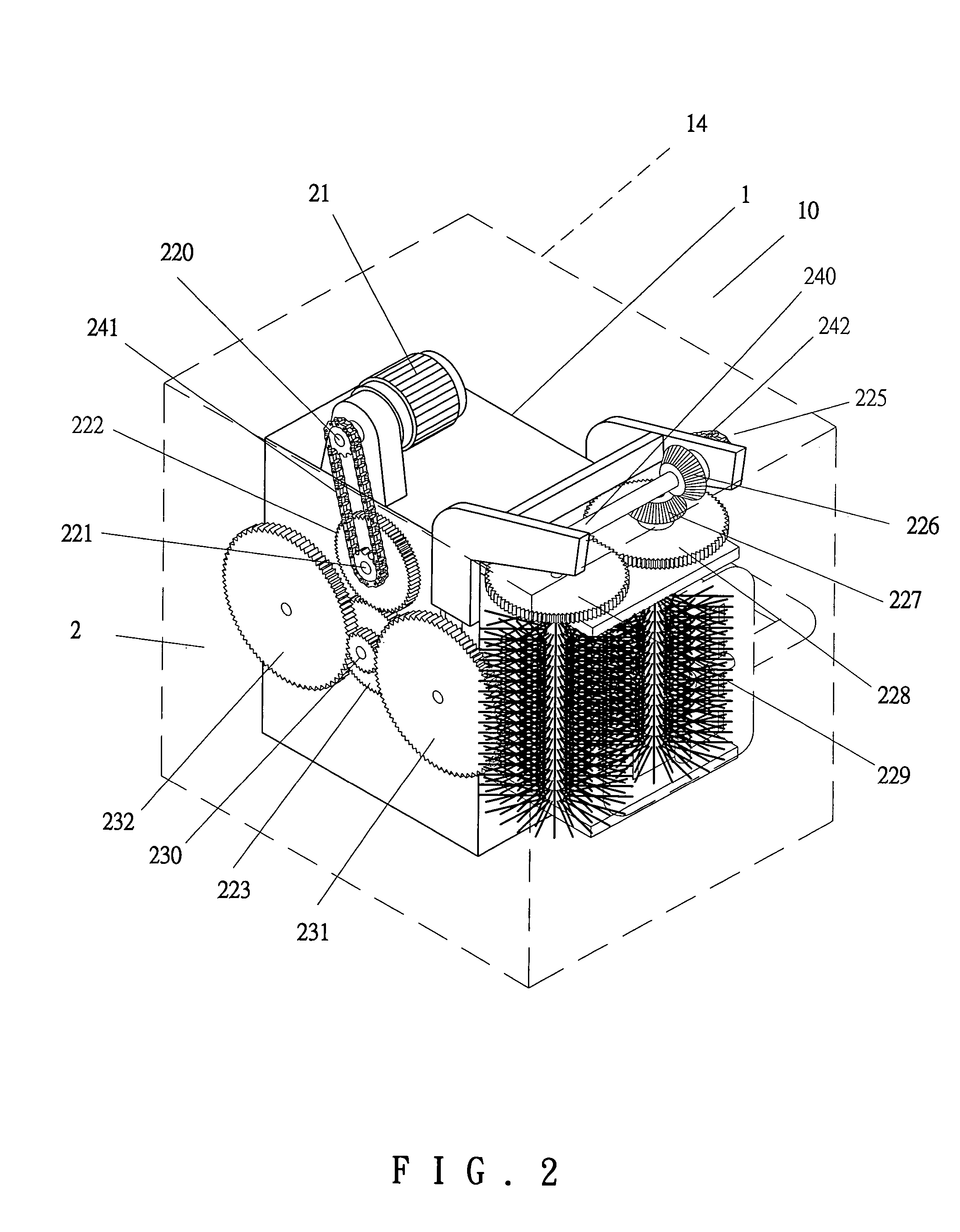
[0027] As illustrated in FIG. 5, the housing 1 comprises a filter cartridge inlet 11 in a front end thereof from which a filter cartridge 6 enters the housing 1. The housing 1 further includes a filter cartridge outlet 12 in a rear end thereof through which the filter cartridge 6 exits the housing 1. The housing 1 further includes a drain 13 in a bottom thereof for draining sewage. An outer casing 14 is mounted outside the housing 1.

[0028] The transmission mechanism 2 includes a motor 21, a gear train including gears 220-232, and a plurality of chains 241 and 242. A gear 220 is mounted on an output shaft (not labeled) of the motor 21 and connected to another gear 221 via a chain 241. The gear 221 moves in synchronism with another gear 222...


PUM


Abstract

A filter cartridge cleaning apparatus includes a housing, a brush mechanism for cleaning a filter cartridge passing through the housing, a guiding mechanism for feeding the filter cartridge toward a filter cartridge outlet of the housing, a water supply mechanism for supplying water to the filter cartridge, and a transmission mechanism for driving the brush mechanism and the guiding mechanism. The housing has a drain for draining sewage resulting from the cleaning process. The filter cartridge cleaning apparatus may be used with a water recycling apparatus to eliminate waste of water.

Description

BACKGROUND OF THE INVENTION [0001] 1. Field of the Invention [0002] The present invention relates to a cleaning apparatus. In particular, the present invention relates to a cleaning apparatus for cleaning filter cartridges. [0003] 2. Description of the Related Art [0004] In a factory for electroplating or using chemicals, it is common to mount a filtering apparatus to a piping system for chemical solutions. The filtering apparatus comprises a filtering device having tubular cartridges for filtering chemical solutions after electroplating process or other chemical processing. Generally, a filtering device used in an electroplating factory comprises tens of filter cartridges that must be cleaned for repeated use. Current cleaning operation for cleaning the filter cartridges is manually carried out one by one, which is time-consuming, and the result is unsatisfactory. Lost occurs due to shutdown of the factory for the long-term cleaning of the filter cartridges in addition to a waste i...

Claims


Application Information

Patent Timeline
IPC IPC(8): B08B1/04
CPCB08B1/02B08B3/022B08B1/04
Inventor GAU, JI-DING
Owner GAU JI DING
Why Eureka
Try Eureka