Vertical mounting of air disk brake caliper assembly

Inactive Publication Date: 2006-10-26
BENDIKS SPAJSER FAUNDEJSHN BREJK LLK
View PDF8 Cites 16 Cited by
  • Summary
  • Abstract
  • Description
  • Claims
  • Application Information

AI Technical Summary

Benefits of technology

[0015] A further advantage of the present invention is the greatly increased serviceability of the brakes. The placement of the mounting frame mounting bolts in the generally perpendicular orientation removes the bolt heads from the highly obstructed area inboard of the axle flange, and places them in locations which are immediately accessible to technicians assembling or servicing the disk brake. In addition, by placing the bolt heads in much more accessible locations above or below the frame/torque plate flanges, the technician is provided with sufficient clearance allow use of high speed, labor-saving power tools for mounting bolt installation and/or removal.
[0016] An additional advantage of orienting the mounting bolts in a radial and/or tangential manner is that the designer is provided additional freedom in defining the interface between the mounting frame and torque plate flanges. In previous pneumatic disk brakes, due to the longitudinal orientation of the mounting bolts and the limited immediately adjacent space, the mounting frame flange which mated against the corresponding torque plate flange containing the mounting bolt holes had to be perpendicular to the axle. With the present invention, the d

Problems solved by technology

The adaptation of disc brake technology to commercial vehicle applications has not been without engineering challenges.
The resulting space envelope between the wheel and its axle is limited, leaving little space available for a pneumatic disc brake.
This lack of available space in turn results in the need to design the brake components, such as mounting flanges (also known as “torque plates”), to conform to the constrained space envelope and avoid interference with nearby vehicle components, such as an immediately adjacent axle flange.
There are several disadvantages to the previous caliper mounting frame arrangements, many of which stem from the configuration of the frame mounting bolts, which are generally parallel to longitudinal axis of the axle.
Achieving sufficient clearance for frame mounting bolt installation and/or removal is problematic due to the close proximity of other vehicle components, such as the axle housing, axle flanges, vehicle suspension (e.g., leaf springs and brackets, shock absorbers and mounts), and steering co

Method used


Image

  • Vertical mounting of air disk brake caliper assembly
  • Vertical mounting of air disk brake caliper assembly
  • Vertical mounting of air disk brake caliper assembly

Examples


Example

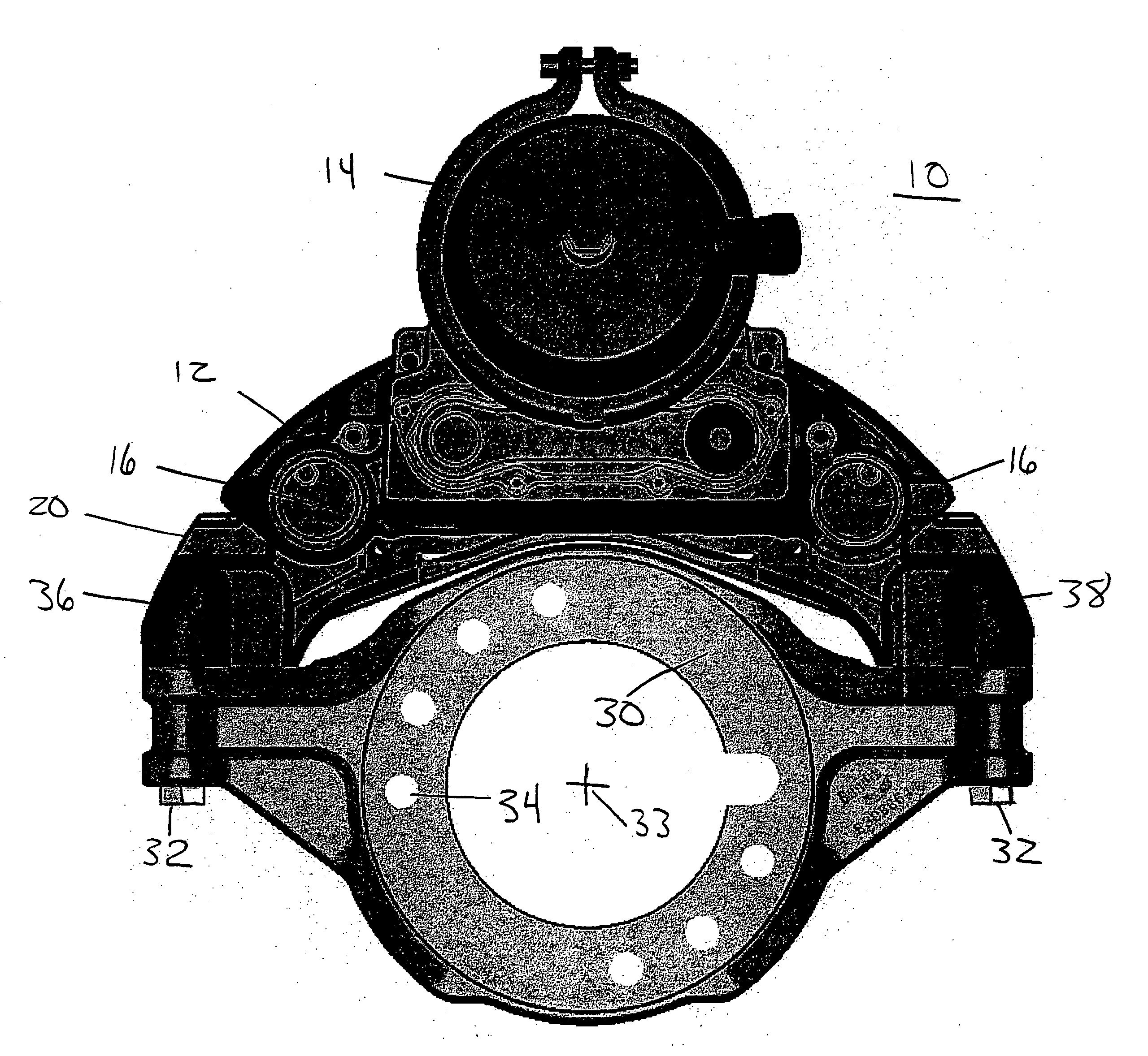
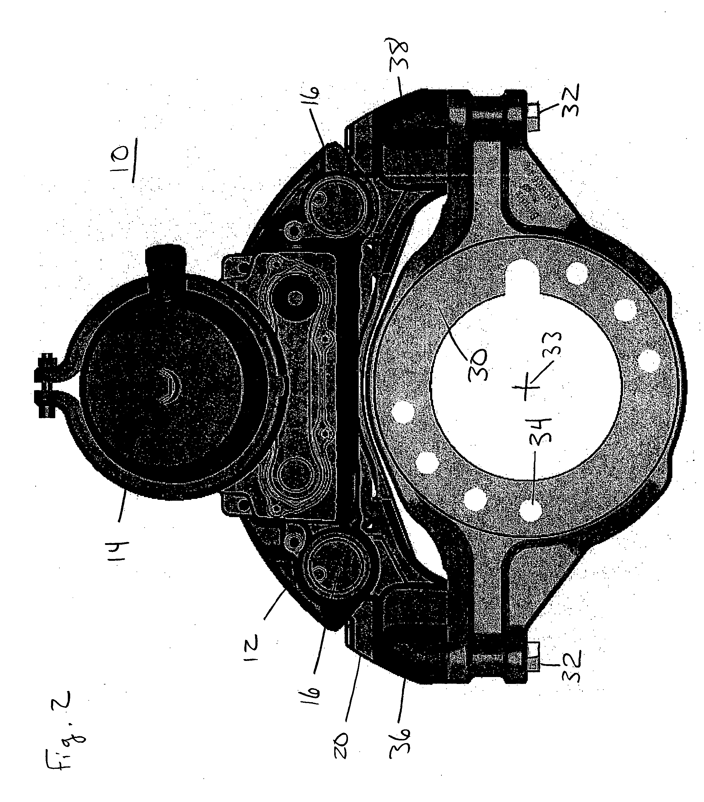
[0026]FIG. 2 is an elevation view looking outward of a first embodiment of a pneumatic disk brake caliper assembly 10 in accordance with the present invention. Additional views of this embodiment are presented in FIGS. 3 and 4.

[0027] In this embodiment, a disk brake caliper 12, with a pneumatic brake actuator 14 mounted thereon, is mounted via pins (located beneath seal covers 16) to a caliper mounting frame 20. Those of ordinary skill in the art will recognize that while the present invention is described herein as including a disk brake caliper with a pneumatic brake actuator, an electric brake actuator may be readily substituted for the pneumatic brake actuator, and such an electrically-actuated brake would be within the scope of the present invention.

[0028] The caliper mounting frame 20 is located in this embodiment on a torque plate 30, and secured by frame mounting bolts 32. As shown in FIG. 3, there are a plurality of mounting bolts 32 at each end of the mounting frame 20, ...


PUM


Abstract

A pneumatically- or electrically-actuated disk brake, in particular a pneumatic disk brake for commercial vehicles, in which a mounting frame which supports the brake caliper, and a torque plate which secures the mounting plate to the a vehicle axle, are arranged such that the fasteners securing the mounting frame to the torque plate are oriented in at least one plane that is essentially perpendicular to a longitudinal axis of the axle. Compared to previous disk brakes with longitudinally-oriented fasteners, this arrangement results in a lighter, stronger, simpler, less expensive, and more easily serviced disk brake by eliminating excess material, eliminating offset of the mounting hole portion of the torque plate to clear an axle flange, minimizing or eliminating a need to rotate the brake assembly away from an optimal position about the axle in order to clear adjacent vehicle components, and places the fastener heads in more readily accessible locations.

Description

BACKGROUND AND SUMMARY OF THE INVENTION [0001] The present invention relates to disk brakes, and in particular to a mounting system for a brake caliper frame assembly of an air disk brake. [0002] Pneumatically-operated disc brakes have been undergoing development and deployment, particularly on commercial vehicles, since at least the 1970's. These disk brakes are beginning to replace drum-style brakes due to advantages in areas such as cooling, fade resistance and serviceability. German patent publication DE 40 32 886 A1, and in particular FIG. 1 of this document, discloses an example of such an air disc brake. [0003] The adaptation of disc brake technology to commercial vehicle applications has not been without engineering challenges. Commercial vehicle wheel rims are sized, both in diameter and axial offset, to provide adequate clearance for the drum-type brakes historically employed on such vehicles. The resulting space envelope between the wheel and its axle is limited, leaving ...

Claims


Application Information

Patent Timeline
IPC IPC(8): F16D55/00
CPCF16D55/226F16D2055/0008F16D2055/0016F16D2121/24F16D2055/0062F16D2121/02F16D2055/002
Inventor BROWN, MICHAEL R. IIBANKS, DANIELHENDERSHOT, JAY ALANPLANTAN, RONALD S.
Owner BENDIKS SPAJSER FAUNDEJSHN BREJK LLK
Why Eureka
Try Eureka