Antennas with multiple feed circuits

Active Publication Date: 2012-05-31
MICROSOFT TECH LICENSING LLC
View PDF9 Cites 11 Cited by
  • Summary
  • Abstract
  • Description
  • Claims
  • Application Information

AI Technical Summary

Benefits of technology

[0011]In simpler embodiments, each feed point and associated pathway is individually switched in by the switch—that is to say, when one feed point and pathway is switched in, all of the others are switched out. However, in more complex embodiments, two or more feed points and associated pathways may be connected at the same time to the input terminal. This provides additional degrees of freedom and to provide a wider bandwidth in some applications.
[0013]In some embodiments, the radiating element, or at least one end thereof, is electrically connected to the groundplane or ground member, either directly (galvanically) or through an inductive and / or capacitive circuit component. This provides an additional degree of freedom which can help match the antenna in particular circumstances.
[0014]In some embodiments, resistive, inductive and / or capacitive circuit components may be placed in series with the radiating element between the feed points. Where there are three or more feed points, different circuit components may be placed in series between different pairs of feed points, or circuit components may be placed between some pairs of feed points and not others. For example, where there is a large difference between two required operating frequency bands, it has been found that placing an inductor in series with the radiating element, between two feed points, can facilitate matching at both bands.

Problems solved by technology

The development of compact antennas capable of operating on all these bands, for use in mobile handsets, laptop computers, trackers and other user equipment (UE) is very challenging.
If the frequency separation is small or the bandwidth is large, then the design of suitable filters and matching circuits becomes difficult—their cost, dimensions and associated transmission losses become unacceptably large.
In the case of mobile radio antennas, the large width of the frequency bands in which f1 and f2 may be positioned, the small fractional separation between the adjacent ends of these frequency bands, and the necessarily small physical dimensions of the antenna (typically 0.2×0.06×0.025 wavelengths) result in an input impedance which is very difficult to match effectively over the specified bands.
The result of inadequate impedance matching is reduced antenna efficiency with consequential reduced range, data rate and battery life.

Method used


Image

  • Antennas with multiple feed circuits
  • Antennas with multiple feed circuits
  • Antennas with multiple feed circuits

Examples


Embodiment Construction

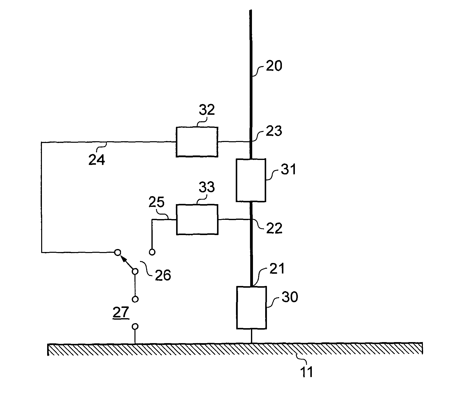
[0029]An improved arrangement is shown in its simplest form in FIG. 3 in which there is provided a conductive antenna member 20 acting in conjunction with a grounded member 11. The end 21 of the conductive antenna member 20 may optionally be connected to the grounded member 11. At least two separate feed points 22, 23 are provided on the antenna member and are connected by a corresponding number of conductors 24, 25 respectively to the input terminal 27 by means of an input switch 26 having the same number of selectable contacts as the number of feed points and connecting conductors which allows the selection of the feed system associated with each frequency band.

[0030]A capacitive circuit component 29 is connected in series in the pathway defined by the conductor 25, and an inductive circuit component 28 is connected in series in the pathway defined by the conductor 24.

[0031]In a further embodiment the end 21 of the antenna conductive member 20 is connected to the groundplane 11 di...


PUM


Abstract

There is disclosed an antenna arrangement comprising an electrically conductive radiating element having first and second ends, an electrically conductive ground plane or ground member, and an input terminal. The radiating element has a plurality of separate feed points at different locations between its first and second ends, and the input terminal is provided with a switch. Each feed point is electrically connected to the switch by way of a separate electrical pathway, the switch being configured to allow the separate feed points to be connected individually or in predetermined combinations to the input terminal by selecting between a plurality of selectable contacts. At least one of the electrical pathways includes a capacitive circuit component connected in series, and at least one other of the electrical pathways includes an inductive circuit component connected in series. The antenna arrangement allows for a high degree of customization and improved matching, and enables good multi-band performance.

Description

[0001]This invention relates to antennas having multiple feed circuits allowing additional circuit elements to be added thereby to improve multiband operationBACKGROUND[0002]The growth of mobile radio applications has led to the development of services using a variety of different air interface standards and radio frequency bands in different parts of the world. A current generation mobile phone is likely to provide for transmissions using the GSM or UMTS air interfaces (as defined by the international standards body 3GPP) on the 850 MHz, 900 MHz, 1800 MHz, 1900 MHz and 2100 MHz frequency bands. The development of compact antennas capable of operating on all these bands, for use in mobile handsets, laptop computers, trackers and other user equipment (UE) is very challenging. The development of antenna techniques has in general been evolutionary, simple dual band structures being progressively optimized to provide wider operating bandwidths at each of the two frequency bands. Current...

Claims


Application Information

Patent Timeline
IPC IPC(8): H01Q1/50
CPCH01Q1/242H01Q9/145H01Q7/00
Inventor COLLINS, BRIANHAPPER, MARC
Owner MICROSOFT TECH LICENSING LLC
Why Eureka
Try Eureka