
Linkage assembly for in-line inspection tool

Active Publication Date: 2010-09-21
PURETECH VENTURES
View PDF30 Cites 23 Cited by
  • Summary
  • Abstract
  • Description
  • Claims
  • Application Information

AI Technical Summary

Benefits of technology

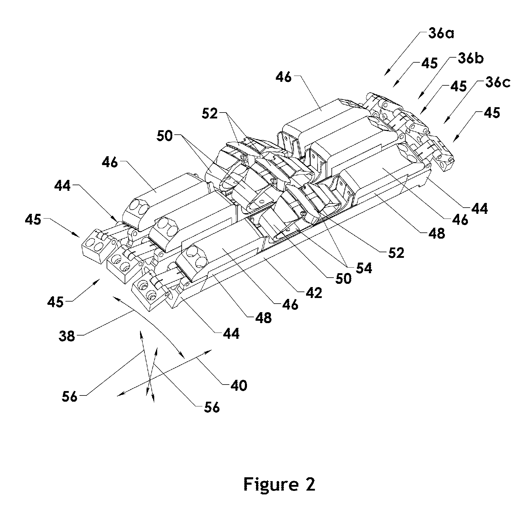
[0012]Linkages may connect an inspection assembly to the rest of an in-line inspection tool. These linkages may hold the inspection assembly in the correct location against the interior surface of the pipeline being inspected and restrict movement of the inspection assembly to a single radial plane (i.e., a plane containing the central axis of the in-line inspection tool). Linkages in accordance with the present invention may support both translational and rotational movement of the inspection assembly within the radial plane. These two degrees of freedom permit the in-line inspection tool to pass bends, changes in diameter, other general pipeline features, circumferential welds, dents, damaged pipe walls and other local pipeline features. Such linkages may also hold an inspection assembly against the interior surface of the pipeline being inspected despite gravitational forces, magnetic forces, and the like that may urge the inspection assembly toward the central axis of the in-line inspection tool.
[0014]In selected embodiments, a leading linkage may include two pivots, while a trailing linkage may comprise three pivots. For example, a leading linkage may comprise a single intermediate section pivotally connected at each end. A trailing linkage, on the other hand, may comprise two pivotally connected intermediate sections. Accordingly, a trailing linkage may provide an additional rotational degree of freedom. In other embodiments, the roles may be reversed and a leading linkage may provide the additional degree of freedom.
[0015]By strictly limiting movement of an inspection assembly to movements within a radial plane, leading and trailing linkages may more precisely control the radial spacing between inspection assemblies. This in turn may produce better data on the pipeline being inspected. By supporting rotation of inspection assemblies within the radial plane, leading and trailing linkages may provide close tracking of the interior surfaces of the pipeline being inspected. Moreover, by relying exclusively on pivots and pivoting, and not slots and sliding, leading and trailing linkages in accordance with the present invention function precisely and repeatably, even in very dirty environments.

Problems solved by technology

Once installed, a pipeline will inevitably corrode or otherwise degrade.
Typical defects of a pipeline may include corrosion, gouges, dents, and the like.
Corrosion may cause pitting or general wall loss, thereby lowering the maximum operating pressure of the pipeline.
Vulnerabilities may also include curvature and bending anomalies, which may lead to buckling, and combined stress and chemical or biological action such as stress corrosion cracking.
Without detection and preemptive action, all such defects and vulnerabilities may lead to pipeline failure.
However, the interior surfaces of pipes are not uniform and the sensors must move relative to the central parts of the inspection tool as the tool passes pipe sections with varying interior surfaces.
These linkages are straightforward, but consume significant space as the assembly collapses on top of the rear linkage.
Accordingly, they have difficulty in accommodating sharp bends in a pipeline.
Furthermore, they must move parallel to their support axis and they can not conform to irregularities such as welds without lifting off from the pipe surface.
These mechanisms cannot precisely control the position of the back end of the assembly.
However, the motion of this last design can be significantly hampered when debris fills the slot or slide.
Local features such as circumferential welds or dents may tend to force an inspection assembly to lift away from the pipe wall.

Method used


Image

  • Linkage assembly for in-line inspection tool
  • Linkage assembly for in-line inspection tool
  • Linkage assembly for in-line inspection tool

Examples


Embodiment Construction

[0025]It will be readily understood that the components of the present invention, as generally described and illustrated in the drawings herein, could be arranged and designed in a wide variety of different configurations. Thus, the following more detailed description of the embodiments of the system and method of the present invention, as represented in the drawings, is not intended to limit the scope of the invention as claimed, but is merely representative of various embodiments of the invention. The illustrated embodiments of the invention will be best understood by reference to the drawings, wherein like parts are designated by like numerals throughout.

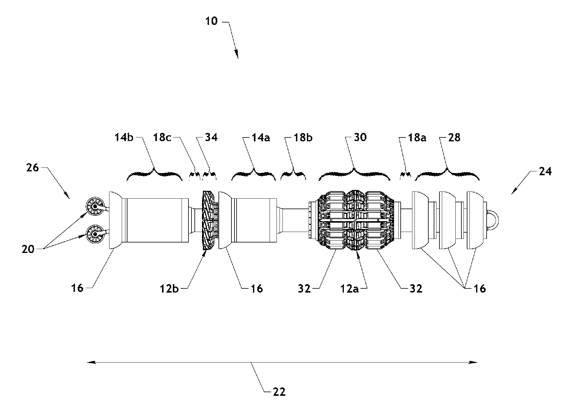
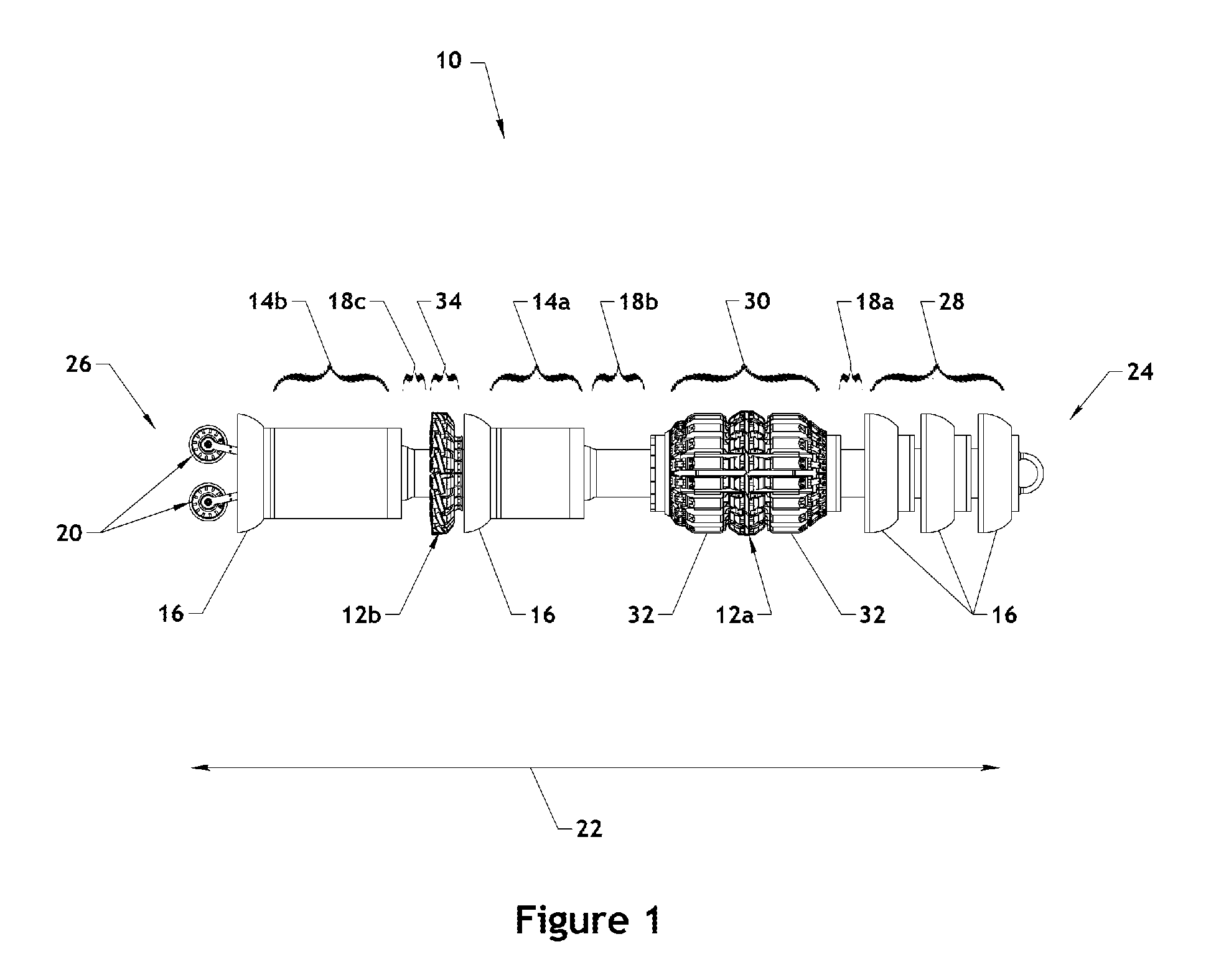
[0026]Referring to FIG. 1, an in-line inspection tool 10 or vehicle 10 in accordance with the present invention may comprise various components including inspection sensors 12, canisters 14, driving cups 16, couplers 18, position sensors 20, and the like. Depending on the configuration of the in-line inspection tool 10 and the si...


PUM


Abstract

An in-line inspection tool comprising sensors mounted on inspection assemblies is disclosed. Each inspection assembly may be connected to the rest of the in-line inspection tool by two linkages. A first linkage may pivotally connect at one end thereof to a first end of an inspection assembly and pivotally connect at the other end thereof to the rest of the in-line inspection assembly. A second linkage may pivotally connect at one end thereof to a second end of the inspection assembly and pivotally connect at the other end thereof to the rest of the in-line inspection tool. The second linkage may comprise a first section and a second section pivotally connected to one another. Accordingly, the first and second linkages may support, exclusively through pivoting, both translational and rotational movement of the inspection assembly within a radial plane containing the central axis of the in-line inspection tool.

Description

RELATED APPLICATIONS[0001]This application is a continuation-in-part of U.S. patent application Ser. No. 12 / 192,030 filed Aug. 14, 2008 now abandoned, which claims the benefit of U.S. Provisional Patent Application Ser. No. 61 / 065,462 filed Feb. 11, 2008. U.S. patent application Ser. No. 12 / 192,030 and U.S. Provisional Patent Application Ser. No. 61 / 065,462 are hereby incorporated by reference.FIELD OF THE INVENTION[0002]This invention relates to pipeline inspection tools, and more particularly to apparatus and methods for linking sensors or inspection assemblies to an in-line inspection tool.BACKGROUND OF THE INVENTION[0003]Oil, petroleum products, natural gas, hazardous liquids, and the like are often transported using pipelines. The majority of these pipelines are constructed from steel pipe. Once installed, a pipeline will inevitably corrode or otherwise degrade. Proper pipeline management requires identification, monitoring, and repair of defects and vulnerabilities of the pipe...

Claims


Application Information

Patent Timeline
IPC IPC(8): G01M19/00G01M99/00
CPCF16L55/28G01M3/005
Inventor HOYT, PHILIP M.FOX, ARTHUR K.
Owner PURETECH VENTURES
Learn More