
Utility pole installation system and method

Inactive Publication Date: 2005-07-28
ANCELL PERRY WAYNE
View PDF15 Cites 14 Cited by
  • Summary
  • Abstract
  • Description
  • Claims
  • Application Information

AI Technical Summary

Benefits of technology

[0023] (9) To permit the efficient installation of lighter utility poles constructed of FIBERGLAS®, aluminum, steel, and other lightweight materials.
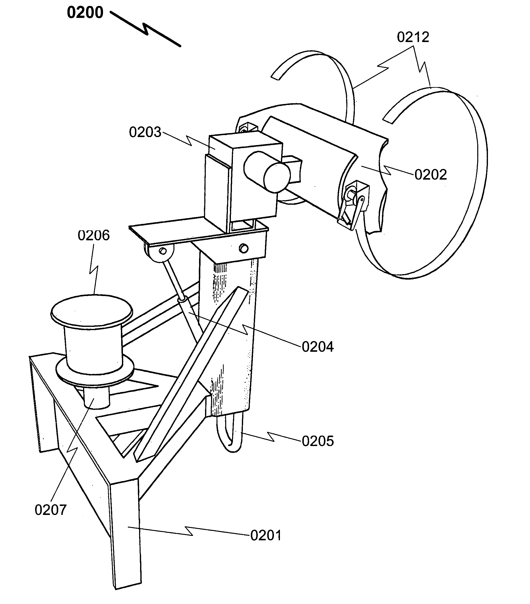
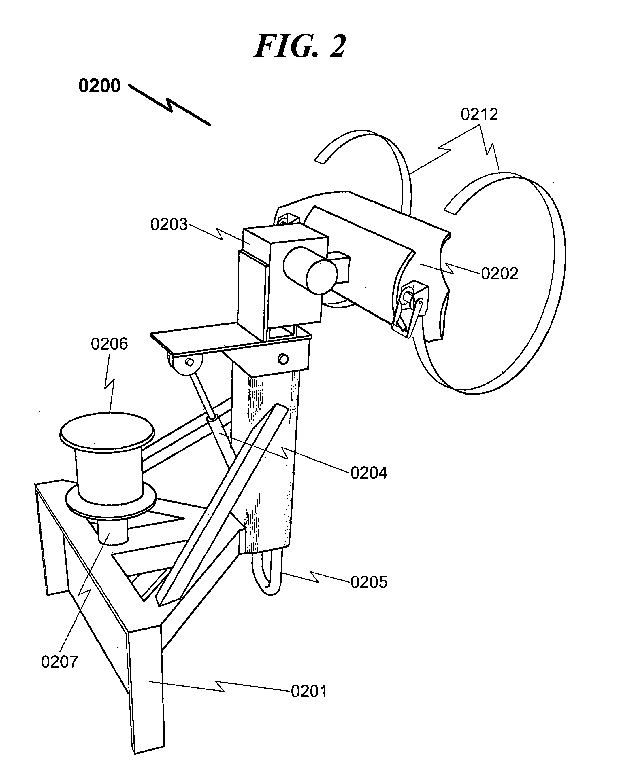
[0034] As seen in FIG. 4 (0400) and detailed in FIG. 5 (0500), FIG. 6 (0600) and FIG. 7 (0700), the combination of the rotating motor means and the articulating piston means permits the pole attachment means to be moved with several degrees of freedom. Additionally, the uni-loader may lift or drop the present invention and thus provide additional degrees of freedom to manipulate the utility pole in space constrained environments, as generally illustrated in FIG. 8 (0800).

Problems solved by technology

This approach may damage or destroy a number of trees and other vegetation resulting in harm to the environment as a result of the installation process.
As a result, the installation of utility poles in these environments results in a significant loss of natural resources in the form of trees and other vegetation which is irreversible as the prior art makes no provision for restoration of these natural resources upon installation of the utility pole.
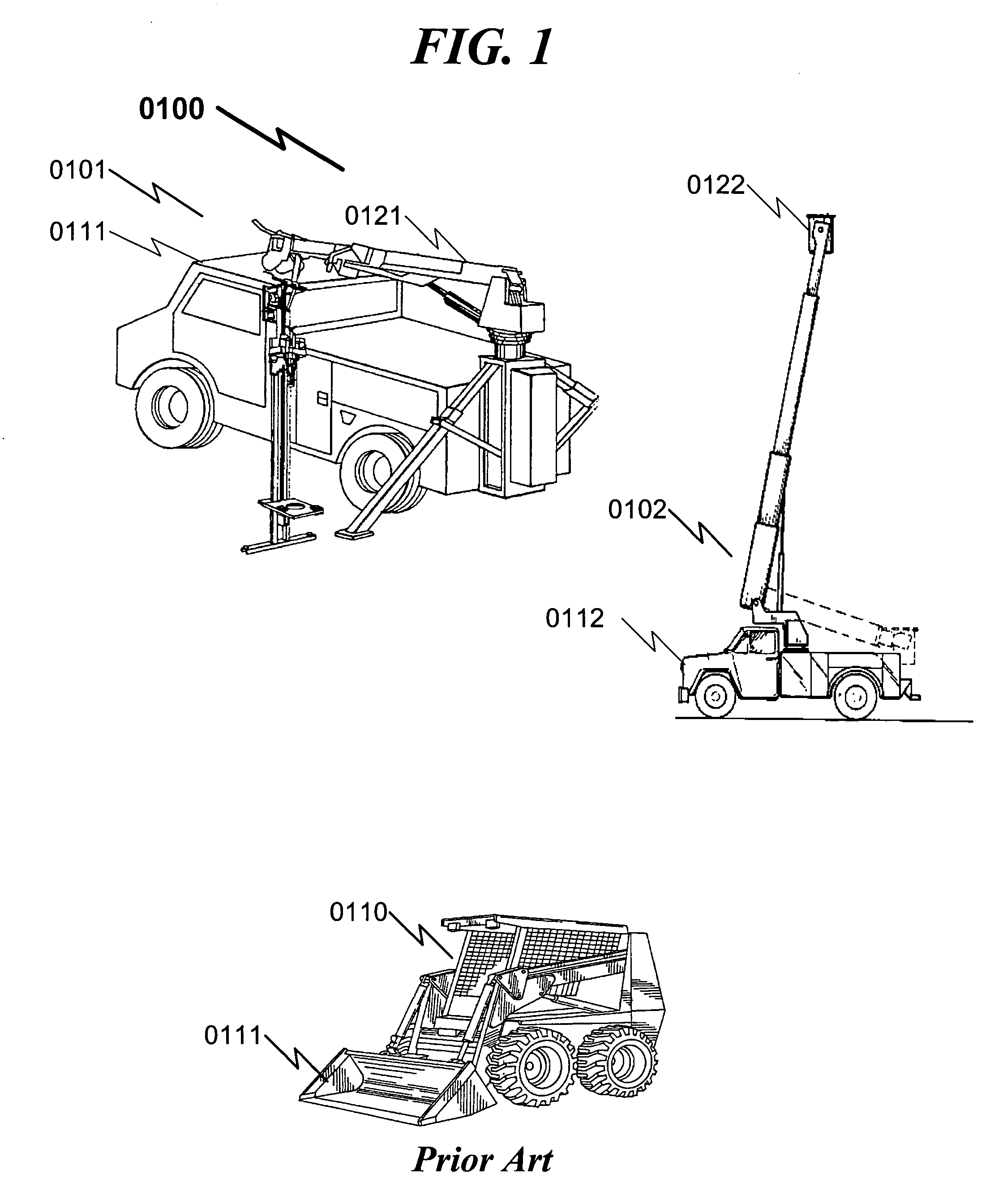
The issue with existing utility pole methods is that the motorized equipment needed for the installation is generally large and cumbersome.
As a result, it is not possible to position this equipment in space constrained areas (wooded backyards, etc.) where new utility pole installations or replacement installations are required.
Additionally, existing utility pole installation devices are generally limited to one of several functions: pole placement and / or hole drilling (0121) for the utility pole or placement / positioning of pole installation personnel (0122).
As a result, multiple tools are generally required for utility pole installation using the prior art.
Furthermore, the prior art generally does not address installation of heavy equipment on the utility pole after the utility pole has been placed.

Method used


Image

  • Utility pole installation system and method
  • Utility pole installation system and method
  • Utility pole installation system and method

Examples


embodiment (

Exemplary Drilling Embodiment (0900, 1000)

[0067]FIG. 9 (0900) and FIG. 10 (1000) illustrate how the present invention may be used with a drilling attachment (0901) to affect the drilling of earthen holes (1009) for use with utility pole placement. Here the pole drilling bit (0901) is attached to a rotating motor means (0902) used to provide torque to spin the drill bit (0901) and affect hole (1009) placement.

[0068] Note that FIG. 9 (0900) and FIG. 10 (1000) illustrate the use of a separate rotating motor means (0902) to place the drill bit (0901). However, it may be possible in some situations to use the same rotating motor means (0203) used to articulate and place the utility pole (the pole attachment means (0202)) to provide torque to the drill bit (0901). In this embodiment the pole attachment means (0202) is removed from the rotating motor means (0203) and the drill bit (0901) is attached directly to the rotating motor means (0203). The illustration provided here is just anothe...


PUM


Abstract

A utility pole installation system and method is disclosed which permits utility poles to be installed via the use of a uni-loader or similar device in areas that are space constrained. Specifically, the present invention is advantageously applied to situations where thick brush or other vegetation makes installation and / or replacement of utility poles difficult. The present invention integrates the utility pole installation function by permitting a single uni-loader attachment to (a) drill the earth holes necessary for utility pole installation, (b) place the utility pole in the drilled earthen hole, (c) install necessary guy wire anchors necessary to maintain utility pole stability, and (d) lift transformers and / or other equipment to the top of the utility pole for attachment to the utility pole. The present invention incorporates a structural frame for attachment to a uni-loader, a pole attachment means coupled with a rotating motor means and an articulating piston means to permit manipulation of the utility pole in multiple degrees of freedom, permitting placement of the utility pole in space constrained environments, such as those associated with replacement of existing utility poles or other utility structures.

Description

CROSS REFERENCE TO RELATED APPLICATIONS Provisional Patent Applications [0001] Applicant claims benefit pursuant to 35 U.S.C. § 119 and hereby incorporates by reference Provisional Patent Application for “UTILITY POLE INSTALLATION SYSTEM AND METHOD”, Ser. No. 60 / 507,600, docket PWA-2003-001, filed Sep. 29, 2003, and submitted to the USPTO with Express Mail Label EV188184763US.PARTIAL WAIVER OF COPYRIGHT [0002] All of the material in this patent application is subject to copyright protection under the copyright laws of the United States and of other countries. As of the first effective filing date of the present application, this material is protected as unpublished material. [0003] However, permission to copy this material is hereby granted to the extent that the copyright owner has no objection to the facsimile reproduction by anyone of the patent documentation or patent disclosure, as it appears in the United States Patent and Trademark Office patent file or records, but otherwise...

Claims


Application Information

Patent Timeline
IPC IPC(8): B66D1/36B66F9/065B66F9/18E02F3/06E02F3/34E02F3/96
CPCB66F9/065B66F9/18E02F3/96E02F3/34E02F3/06
Inventor ANCELL, PERRY WAYNE
Owner ANCELL PERRY WAYNE
Learn More