Seal structure for a wire-cut electric discharge machine

a sealing structure technology, which is applied in the direction of machines/engines, transportation and packaging, brake systems, etc., can solve the problems of virtually impossible to eliminate completely the leakage of machining fluid using such a sealing structure, and the leakage can occur on all sides, so as to facilitate collection and improve the reliability of the wire-cut electric discharge machine

Active Publication Date: 2006-10-26
FANUC LTD
View PDF13 Cites 10 Cited by
  • Summary
  • Abstract
  • Description
  • Claims
  • Application Information

AI Technical Summary

Benefits of technology

[0016] The present invention provides a seal structure capable of controlling the routes of leakage of machining fluid from the machining tank so as to facilitate countermeasure of machining fluid leakage from the machine. In addition, by enabling the machining fluid collection structure to be simplified, the present invention improves the reliability of the wire-cut electric discharge machine by inexpensive means.
[0021] Unlike existing seal structures, the present invention enables the locations of leakage to be identified and localized, thus facilitating collection of machining fluid draining from the machining tank to be collected without leaking to the outside of the machine. Moreover, the foregoing arrangement enables the present invention to improve the reliability of the wire-cut electric discharge machine without inviting a cost increase.

Problems solved by technology

The problem with this sort of seal structure is leakage of the machining fluid from between the seal plate 4 and the seal 3.
Although it is true that using a seal 3 of such a construction can reduce the amount of leakage of the machining fluid to some extent, as a practical matter, it is virtually impossible to eliminate completely the leakage of machining fluid using such a seal structure.
Consequently, a certain amount of flowage of machining fluid to the outside of the machining tank is considered inevitable, and therefore efforts to alleviate this problem are currently limited to providing means for recovering the machining fluid that thus drains away.
In reality, however, experience shows that, as shown by the numerous arrows 6 shown in FIG. 2, leaks can occur on all sides.
If such a machining fluid leakage outside the machine occurs, it can degrade the surrounding environment and require that the machine be shut down.
Such a problem is difficult to solve using the unevenly shaped labyrinth seal structure like that disclosed for example in JP 3026120B for the seal.
In addition, although a conventional technique of providing a wiper-like member on the sides of the seal unit to prevent leakage to the outside the machine in order to prevent machining fluid leakage from the top and the sides of the seal and along the seal plate 4 from leaking outside of the machine, is well known, such an arrangement has the disadvantage that the structure of the seal unit becomes complicated, inviting an increase in cost.

Method used


Image

  • Seal structure for a wire-cut electric discharge machine
  • Seal structure for a wire-cut electric discharge machine
  • Seal structure for a wire-cut electric discharge machine

Examples


Embodiment Construction

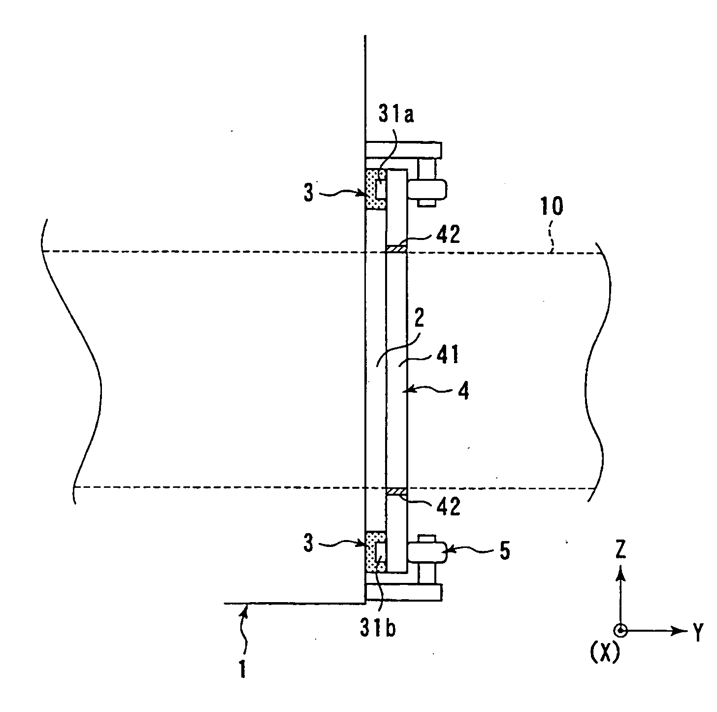
[0032] A detailed description will now be given of embodiments and variations of the present invention, with reference to the accompanying drawings. It should be noted that, except for the difference in seals employed, the basic construction of the seal structure shown in FIG. 1 can be employed in all cases described below, and accordingly, a description of the basic construction of the seal structure shown in FIG. 1 is not repeated.

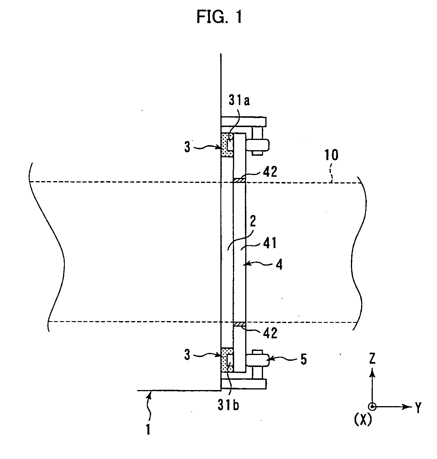
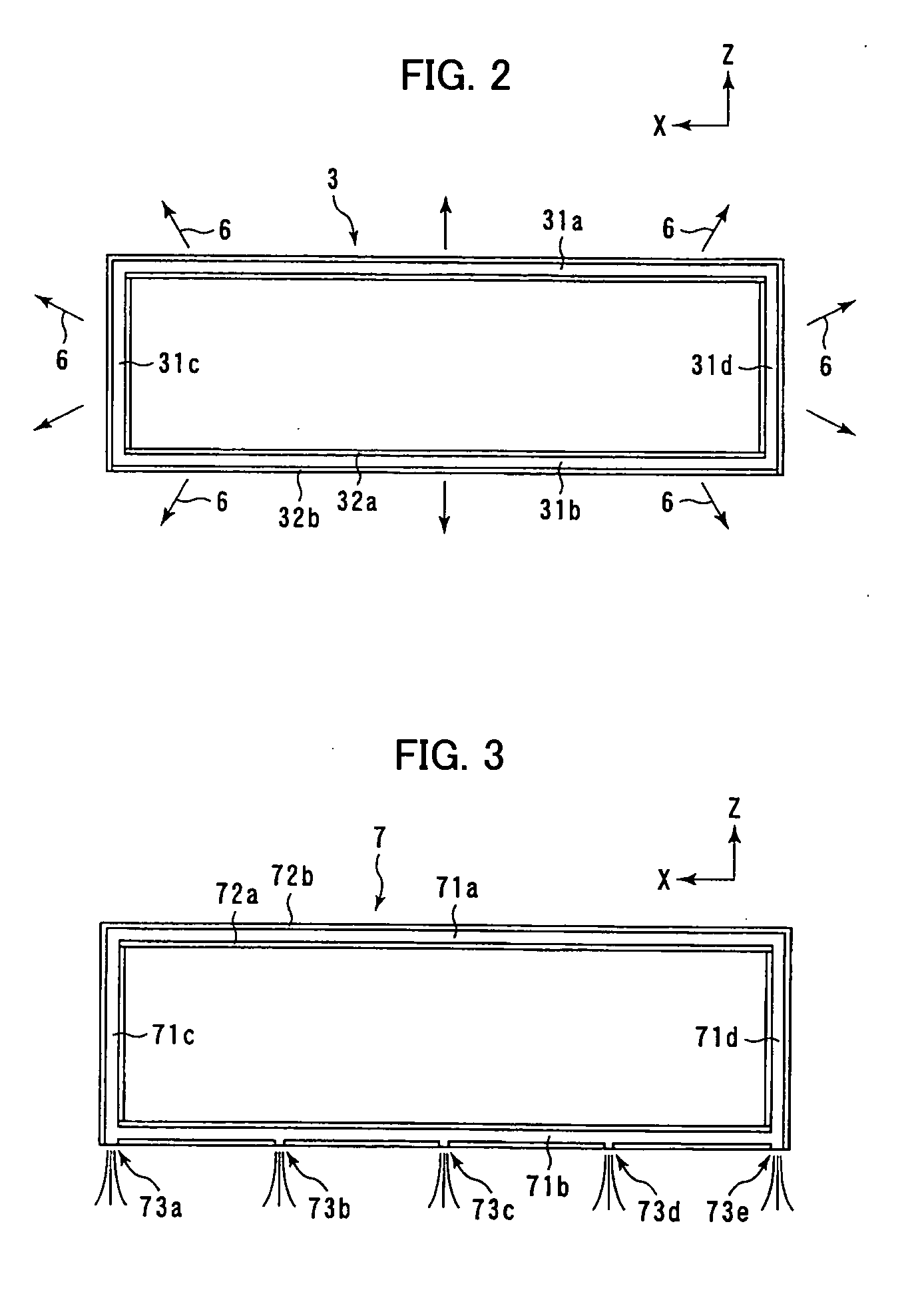
[0033] First, in a typical embodiment, a structure is employed in which a first seal means (that is, seal 3) employed in the structure shown in FIG. 1 is substituted for a seal 7 shown in FIG. 3. In FIG. 3, as in FIG. 2, the seal (first seal means) 7 is shown in plan view, as seen from the ±Y direction shown in FIG. 1. As shown in FIG. 3, as with seal 3, an unevenly shaped part composed of two ridges and one groove is formed in a side of the seal 7 that contacts the seal plate 4 (see FIG. 1)

[0034] In addition, that the seal 7 has a frame-like shape aro...


PUM

PropertyMeasurementUnit
intersecting angleaaaaaaaaaa
lengthaaaaaaaaaa
forceaaaaaaaaaa

Abstract

A seal structure that channels drainage of machining fluid from the periphery of an opening for a lower arm of a wire-cut electric discharge machine. A seal structure that restricts flowage to the outside of machining fluid through the opening (slot) in a side of a machining tank has a first seal means and a second seal means (a seal plate) affixed to the first seal means so as to cover the opening. An unevenly shaped part including ridges and grooves extending in the long direction of the first seal means is formed on the first seal means, and passages are provided that communicate with the groove and the outside to channel the machining fluid drainage path. The first seal means may be composed of a plurality of members. The passages are provided by notches or through-holes formed in a ridge, or by through-holes extending from the groove to the exterior of the first seal means without passing through the ridges. Suction means that sucks up machining fluid draining from the passages may be provided.

Description

BACKGROUND OF THE INVENTION [0001] 1. Field of the Invention [0002] The present invention relates to a seal structure for a wire-cut electric discharge machine, and more particularly to a seal structure that restricts flowage to the outside of machining fluid from an opening in a side wall of a machining tank that permits the passage of a lower arm therethrough. [0003] 2. Description of the Related Art [0004] As is well known, in a wire-cut electric discharge machine, machining is carried out by supporting a wire electrode between upper and lower arms and causing an electric discharge between a workpiece and the wire electrode, in a state in which the workpiece is immersed in machining fluid. The machining fluid is contained in a machining tank, and an opening that permits the passage of the lower arm is provided in a side surface of the machining tank. In order to prevent the loss of machining fluid to the outside through this opening, a seal structure that restricts the flowage of...

Claims


Application Information

Patent Timeline
Patent Type & Authority Applications(United States)
IPC IPC(8): F16J9/00B23H7/00F16J15/52
CPCB23H7/02
Inventor KITA, YUKIOKUDA, SHINJIYAMANE, HIKARU
Owner FANUC LTD
Why Eureka
Try Eureka