Arrangement structure for auxiliary component of vehicle

a technology for auxiliary components and arrangement structures, applied in child seats, roofs, transportation and packaging, etc., can solve problems such as reducing the size of auxiliary components of vehicles, and achieve the effect of improving layout flexibility

Inactive Publication Date: 2006-10-26
MAZDA MOTOR CORP
View PDF10 Cites 15 Cited by
  • Summary
  • Abstract
  • Description
  • Claims
  • Application Information

AI Technical Summary

Benefits of technology

[0013] In the arrangement structure set forth in the first aspect of the present invention, a large-size interior component can be placed on the first kick-up portion. Further, an auxiliary component can be arranged below the second kick-up portion, and a small-size interior component can be placed on the second kick-up portion. This makes it possible to provide enhanced layout flexibility in a limited vehicle space. In other words, the present invention allows for a desirable vehicle design capable of satisfying both of a low overall-height compact body and an adequate arrangement of the auxiliary component.

Problems solved by technology

This hinders downsizing the vehicle.

Method used


Image

  • Arrangement structure for auxiliary component of vehicle
  • Arrangement structure for auxiliary component of vehicle
  • Arrangement structure for auxiliary component of vehicle

Examples


first embodiment

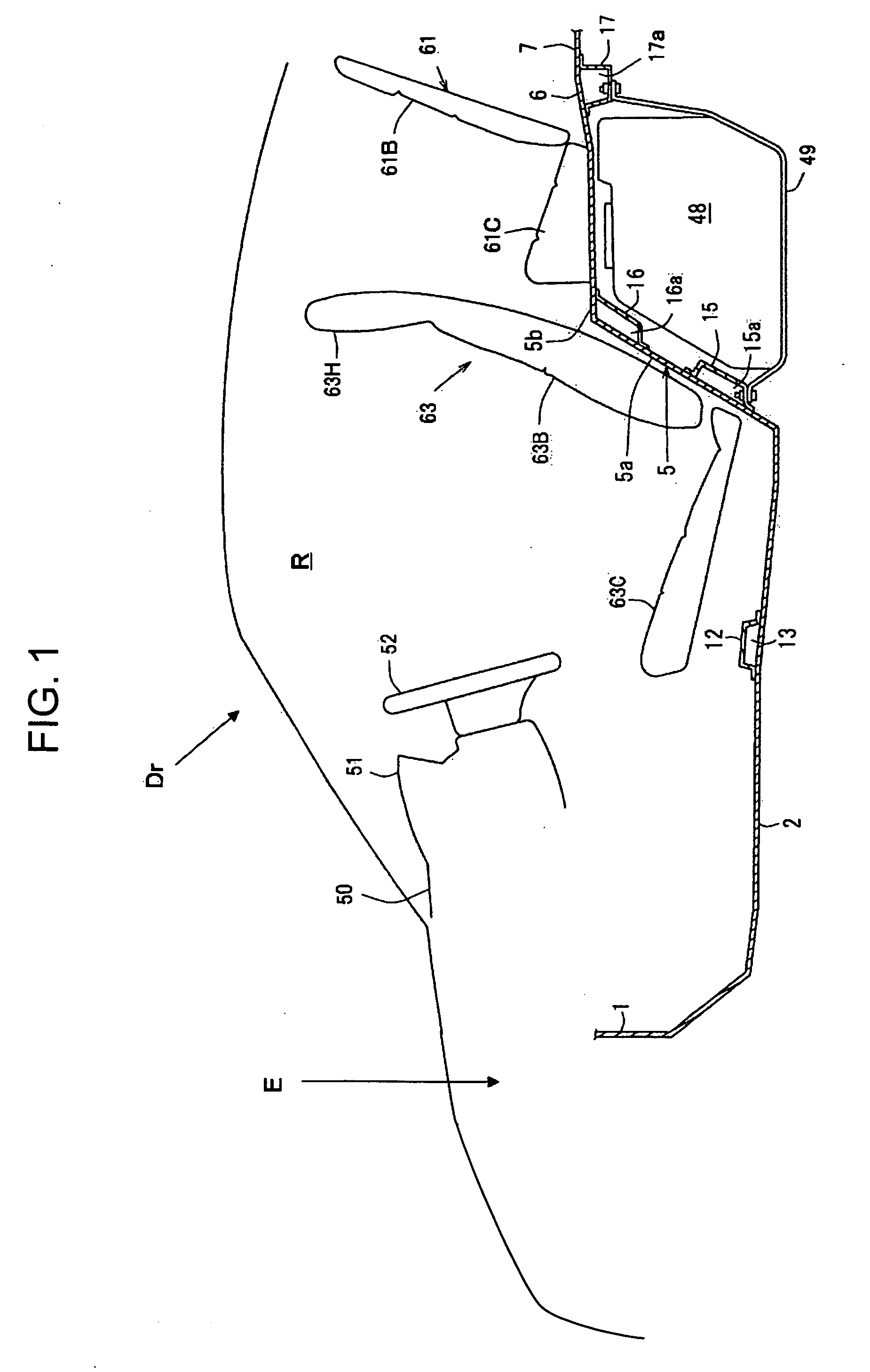
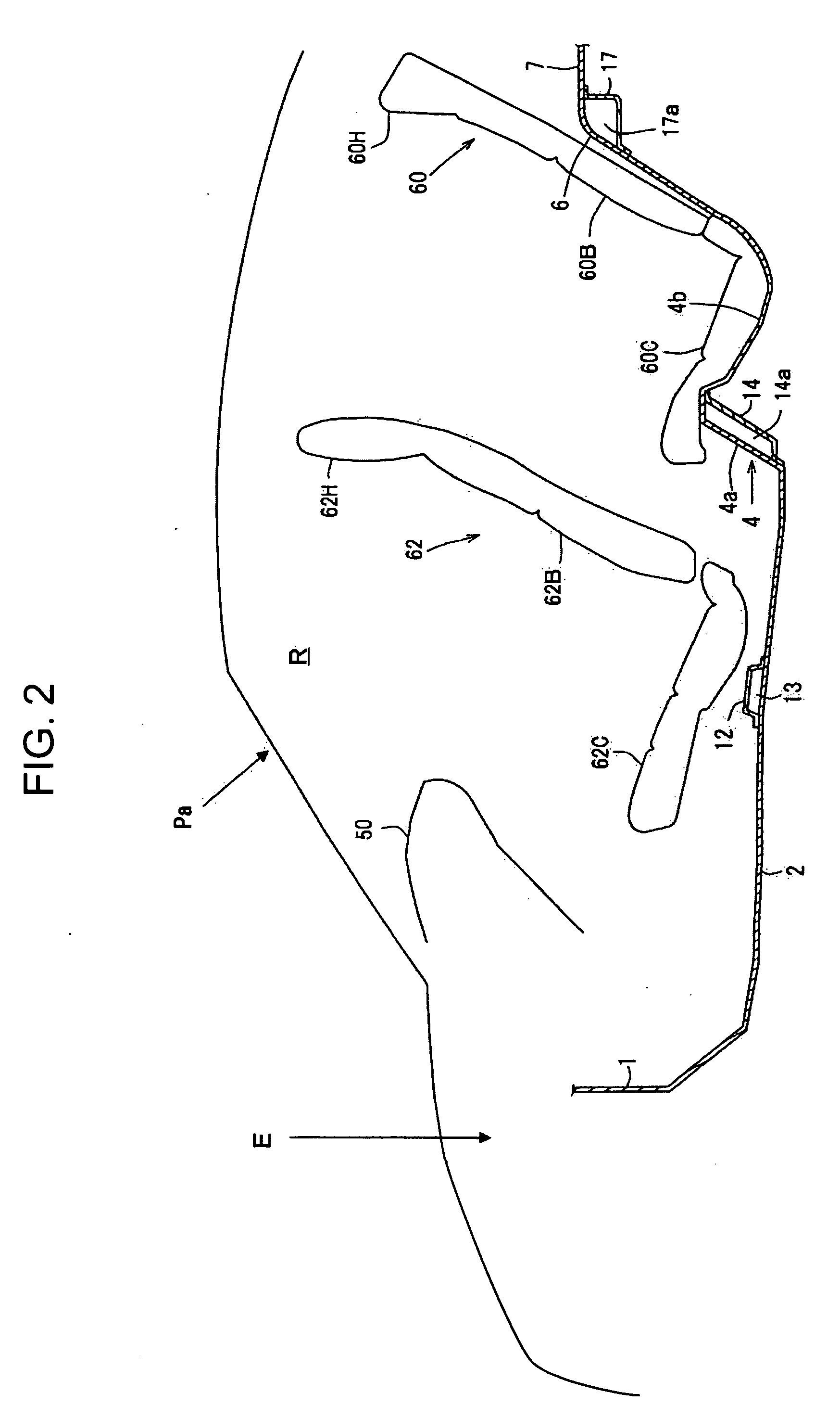
[0059] With reference to the drawings, the present invention will now be described.

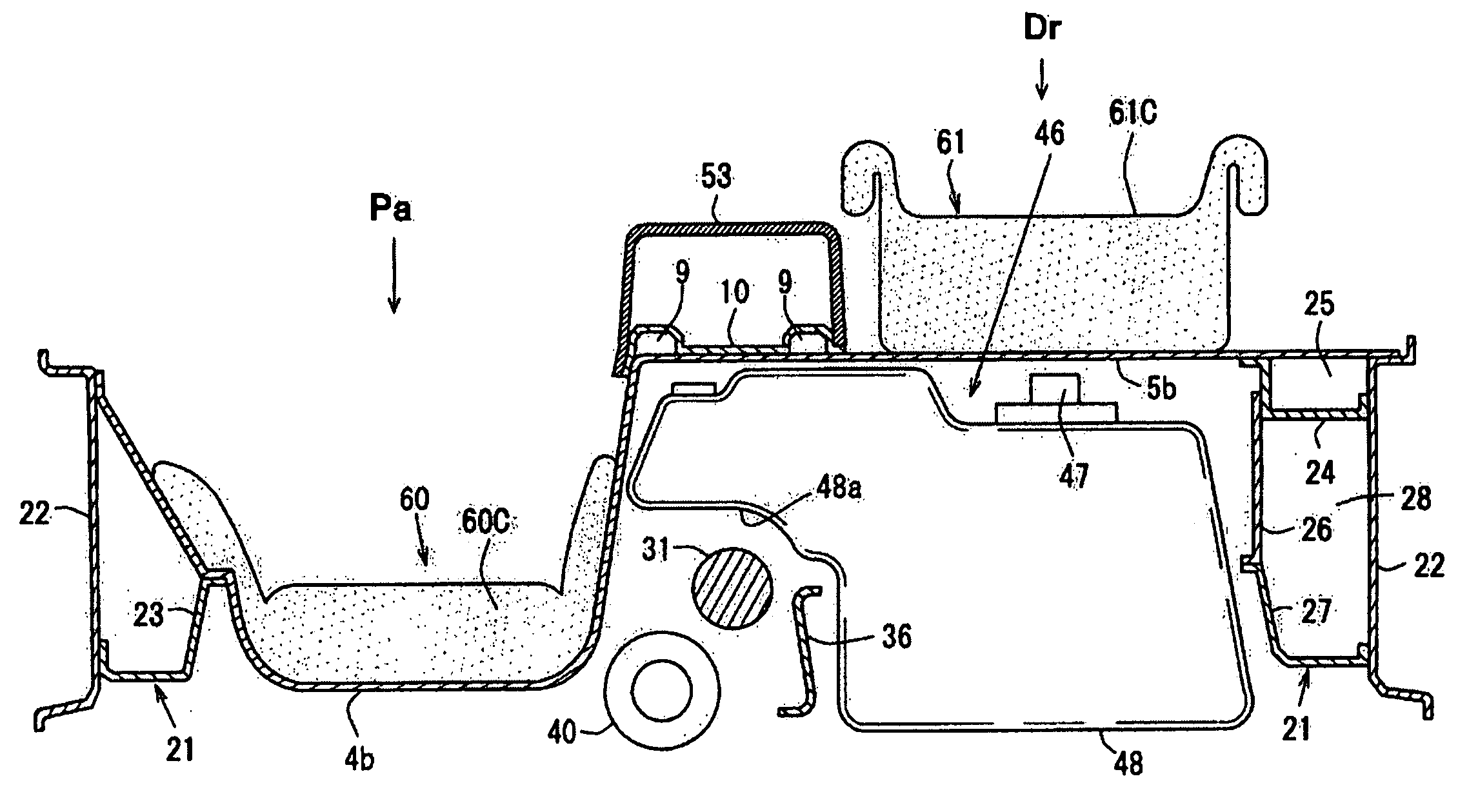
[0060]FIGS. 1 and 2 are side views showing an arrangement structure for an auxiliary component of a vehicle, according to the first embodiment, viewed, respectively, from the side of a driver's seat Dr and from the side of a front passenger seat Pa.

[0061] A lower dash panel (dash panel) 1 is disposed in a front region of a vehicle to partition between an engine compartment E and a passenger compartment R in a frontward / rearward or longitudinal direction of a vehicle body. A floor panel 2 is connected to a rear side of a lower edge of the lower dash panel 1 to extend approximately horizontally toward a rear region of the vehicle. The floor panel 2 defines a lower surface (bottom surface) of the passenger compartment R.

[0062]FIG. 3 is a perspective view showing the floor panel 2. The floor panel 2 has a kick-up area 3 stepped upward in a rear region thereof. The kick-up area 3 includes a first kick-up...

second embodiment

[0107] With reference to the drawings, the present invention will be described below.

[0108]FIG. 18 is a side view showing an arrangement structure for an auxiliary component of a vehicle, according to the second embodiment, viewed from the driver's-seat side Dr, and FIG. 19 is a detail view showing the auxiliary-component arrangement structure in FIG. 18. FIG. 20 is a side view showing the auxiliary-component arrangement structure in FIG. 18, viewed from the front-passenger-seat side Pa. FIG. 21 is a perspective view showing a floor panel 2, and FIG. 22 is a top plan view showing a passenger compartment of the vehicle in FIG. 18.

[0109] As with the first embodiment, a bottom surface of a passenger compartment R is defined by the floor panel 2. The floor panel 2 has a rear region formed as a first kick-up portion 4 on the front-passenger-seat side Pa and a second kick-up portion 5 on the driver's-seat side Dr, and the second kick-up portion 5 is formed to have a height greater than t...


PUM


Abstract

Disclosed is an arrangement structure for an auxiliary component of a vehicle, which comprises a floor panel defining the bottom surface of the passenger compartment and having a first kick-up portion and a second kick-up portion disposed in side-by-side relation to the first kick-up portion in a lateral direction of a vehicle body and formed to have a height greater than that of the first kick-up portion, a first seat disposed on the first kick-up portion, a second seat formed to have a smaller size than that of the first seat and disposed on the second kick-up portion, and a cross member joined along the second kick-up portion in the lateral direction to form a closed section therebetween. The auxiliary component includes a first fuel tank arranged below the first kick-up portion, and a second fuel tank formed to have a height greater than that of the first fuel tank and arranged below the second kick-up portion. The arrangement structure of the present invention allows a vehicle to have a low overall-height compact body while achieving enhanced layout flexibility and assuring a passenger compartment space.

Description

BACKGROUND OF THE INVENTION [0001] 1. Field of the Invention [0002] The present invention relates to an arrangement structure for an auxiliary component of a vehicle component in a region outside of a bottom surface of a passenger compartment of the vehicle. [0003] 2. Description of the Related Art [0004] Heretofore, there has been known an arrangement structure for an auxiliary component of a vehicle, as shown in FIGS. 42, 43 and 44, wherein FIG. 42 is a schematic top plan view of a passenger compartment, and FIGS. 43 and 44 are side views of the arrangement structure, viewed, respectively, from the side of a driver's seat and from the side of a front passenger seat. [0005] Specifically, FIGS. 42, 43 and 44 show an arrangement structure for an auxiliary component of a four-passenger (four-seater) vehicle. In this arrangement structure, a driver's seat 101 and a front passenger seat 102 are disposed right and left on a front region of a floor panel 100 defining a bottom surface of a...

Claims


Application Information

Patent Timeline
Patent Type & Authority Applications(United States)
IPC IPC(8): B62D25/20
CPCB60K13/04B60K15/063B60K15/067B60K15/073B62D25/20B60N2/012B60N2/015B62D25/087B60K2015/03118B60N2/26
Inventor TOHDA, ISAOIWASAKA, KOUJISOGAME, KATSUMASAMORI, SHIGEYUKI
Owner MAZDA MOTOR CORP
Why Eureka
Try Eureka