Piezoelectric composite device, method of manufacturing same, method of controlling same, input-output device, and electronic device

a composite device and piezoelectric technology, applied in the direction of generator/motor, pulse technique, instruments, etc., can solve the problems of difficulty in integrating the two structures described above into one structure, requiring more mounting space, and difficulty in separation of voltages, etc., to achieve the effect of compact electronic devices

Inactive Publication Date: 2006-10-26
MARUYAMA SHIGEAKI +2
View PDF4 Cites 31 Cited by
  • Summary
  • Abstract
  • Description
  • Claims
  • Application Information

AI Technical Summary

Benefits of technology

[0017] It is thus possible to provide the piezoelectric composite device which combines a piezoelectric bimorph type actuator vibrating on the basis of the predetermined voltage supplied between the feeding electrode and the common electrode, and a force detecting sensor outputting the force detection signal based on the external force.
[0057] According to the second electronic device in accordance with an embodiment of the present invention, the second input-output device according to an embodiment of the present invention is applied. Therefore a part of the piezoelectric composite device functioning as a piezoelectric bimorph type actuator can be used as a force detecting sensor. Thus, the function of the actuator and the function of the force detecting sensor can be used at the same time. In addition, as compared with a case where the actuator and the force detecting sensor are provided separately from each other, a mounting space is shared and thus the electronic device can be made more compact.

Problems solved by technology

Hence, the two structures of the force detecting sensor and the actuator need to be attached to the input-output device, thus requiring more mounting space as compared with a case where the structures are integrated into one structure.
However, a difficulty is involved in integrating the two structures described above into one structure.
As compared with this driving command voltage, the voltage (sensor output signal) varied by external force is low, so that the separation of the voltages is technically difficult.
In addition to this, the addition of a complex circuit is expected, which will be disadvantageous from a viewpoint of size and cost of the actuator.

Method used


Image

  • Piezoelectric composite device, method of manufacturing same, method of controlling same, input-output device, and electronic device
  • Piezoelectric composite device, method of manufacturing same, method of controlling same, input-output device, and electronic device
  • Piezoelectric composite device, method of manufacturing same, method of controlling same, input-output device, and electronic device

Examples


first embodiment

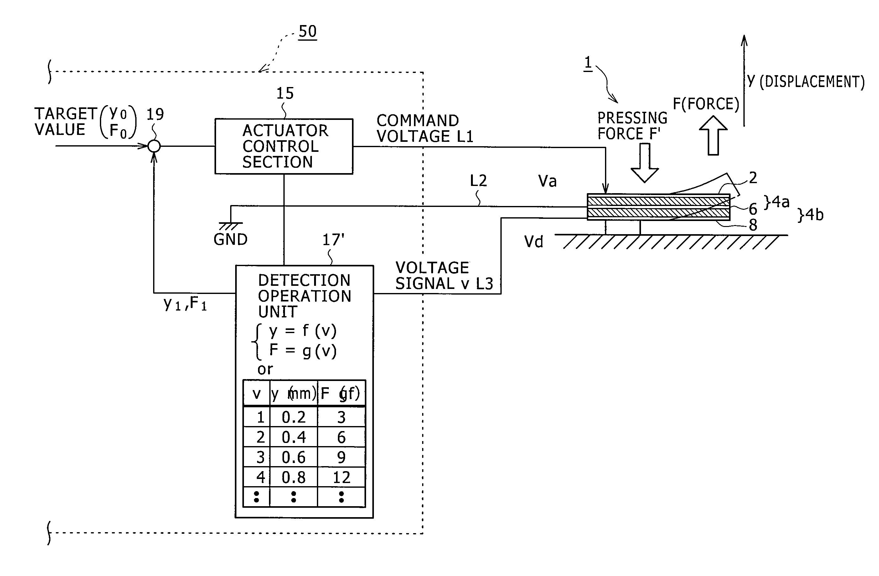
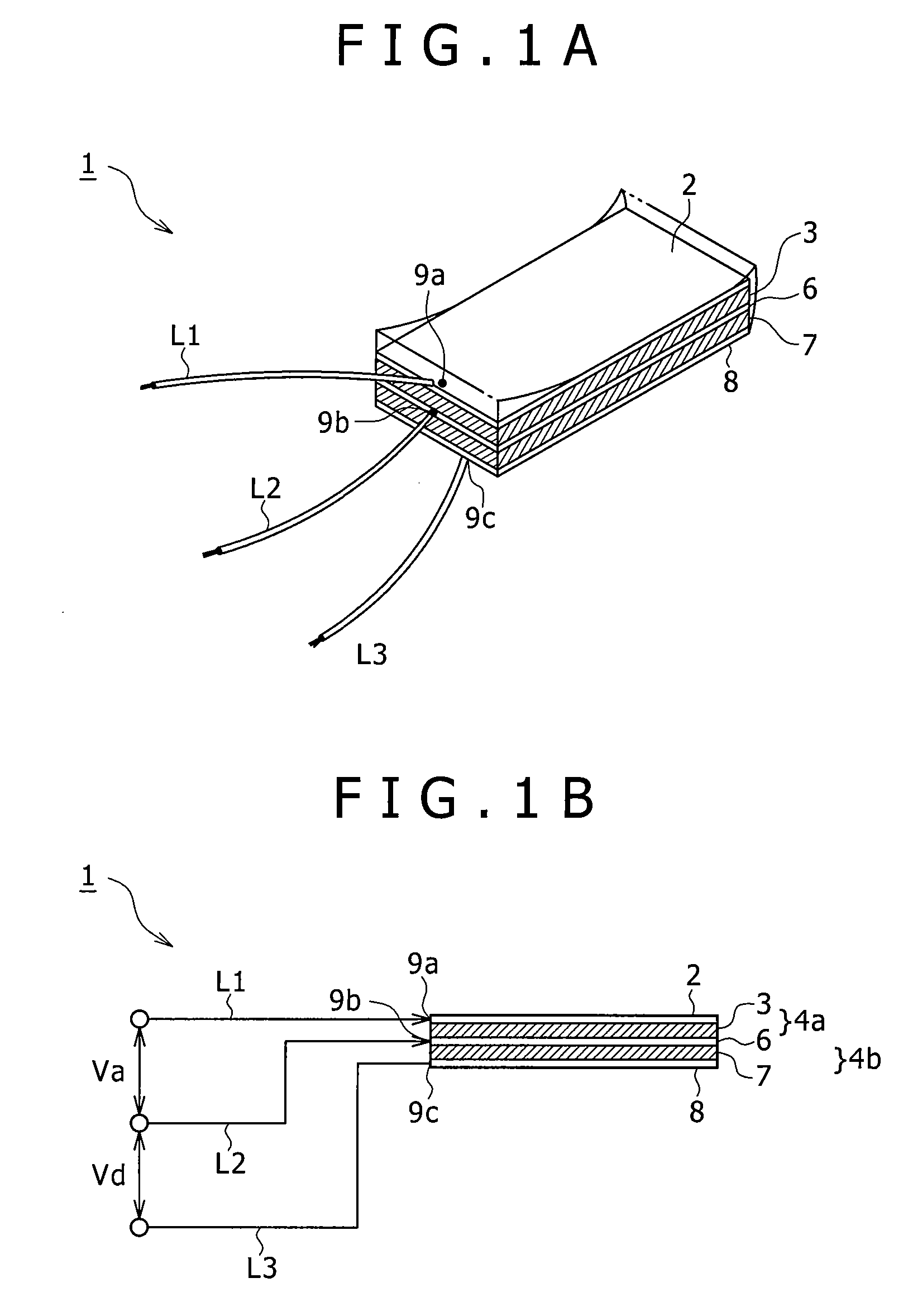
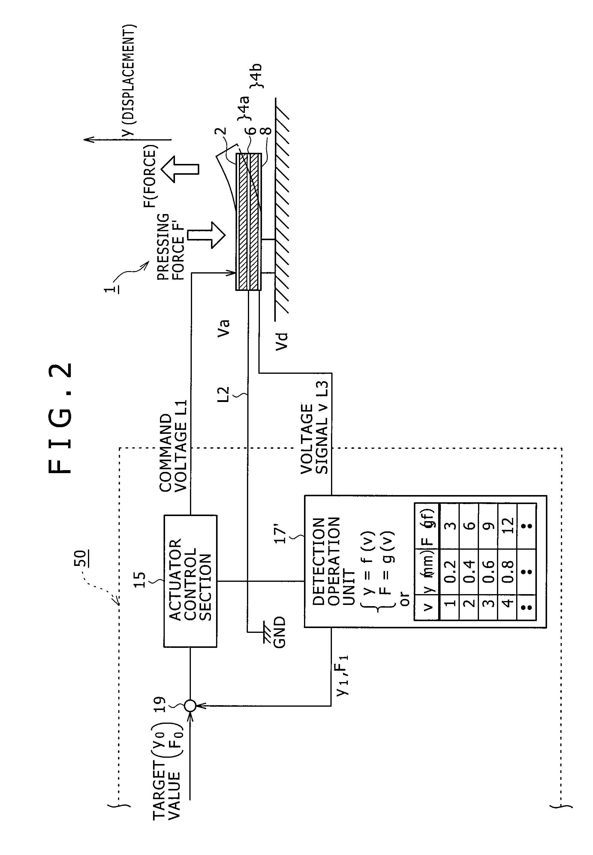
[0086]FIGS. 1A and 1B are a perspective view and a sectional view of an example of structure of a multifunction piezoelectric actuator 1 according to the present invention.

[0087] The first embodiment includes: a first piezoelectric element joined between a feeding electrode and a common electrode; and a second piezoelectric element joined between the common electrode and a signal detecting electrode; wherein a predetermined voltage is supplied between the feeding electrode and the common electrode, and a force detection signal based on an external force is extracted from the detecting electrode. Thus a piezoelectric composite device can be provided which combines a piezoelectric bimorph type actuator vibrating on the basis of the predetermined voltage supplied between the feeding electrode and the common electrode, and a force detecting sensor outputting the force detection signal based on the external force.

[0088] The multifunction piezoelectric actuator 1 of a fixed connection ty...


PUM

PropertyMeasurementUnit
thicknessaaaaaaaaaa
thicknessaaaaaaaaaa
temperatureaaaaaaaaaa

Abstract

Disclosed herein is a piezoelectric composite device including: a feeding electrode; a common electrode; a signal detecting electrode; a first piezoelectric element joined between the feeding electrode and the common electrode; and a second piezoelectric element joined between the common electrode and the signal detecting electrode; a predetermined voltage being supplied between the feeding electrode and the common electrode; and a force detection signal based on an external force being extracted from the detecting electrode.

Description

RELATED APPLICATION DATA [0001] This application is divisional of U.S. patent application Ser. No. 11 / 193,238, filed Jul. 29, 2005, which is incorporated herein by reference to the extent permitted by law. This application claims the benefit of priority to Japanese Patent Application No. JP 2004-227053 filed in the Japanese Patent Office on Aug. 3, 2004, which also is incorporated herein by reference to the extent permitted by law.BACKGROUND OF THE INVENTION [0002] The present invention relates to a piezoelectric composite device, a method of manufacturing the same, a method of controlling the same, an input-output device, and an electronic device that are suitable for application to portable telephones, digital cameras, portable terminals, remote controllers and the like having a tactile input function. [0003] The present invention relates particularly to a piezoelectric composite device including a first piezoelectric element joined between a feeding electrode and a common electro...

Claims


Application Information

Patent Timeline
Patent Type & Authority Applications(United States)
IPC IPC(8): H01L41/107G01L1/16G06F3/041H01H9/16H01H13/712H01L41/08H01L41/09H01L41/22H01L41/27H01L41/313
CPCG06F3/011G06F3/016H01L41/0474H03K17/9643H01L41/083H01L41/273H01L41/0825G06F2203/04105H10N30/874H10N30/1071H10N30/50H10N30/053
Inventor MARUYAMA, SHIGEAKISEKINE, JUNICHIPOUPYREV, IVAN
Owner MARUYAMA SHIGEAKI
Why Eureka
Try Eureka