Eureka AIR delivers breakthrough ideas for toughest innovation challenges, trusted by R&D personnel around the world.

Vertical speed and flight path command module for displacement collective utilizing tactile cueing and tactile feedback

a technology of displacement and command module, applied in vehicle position/course/altitude control, process and machine control, instruments, etc., can solve the problems of complicated single axis input, limited method benefit of handling qualities, and difficulty in implementing a collective controller with vertical augmentation. achieve the effect of reducing pilot workload, increasing situation awareness, and increasing handling qualities

Active Publication Date: 2011-04-19
SIKORSKY AIRCRAFT CORP
View PDF44 Cites 40 Cited by
  • Summary
  • Abstract
  • Description
  • Claims
  • Application Information

AI Technical Summary

Benefits of technology

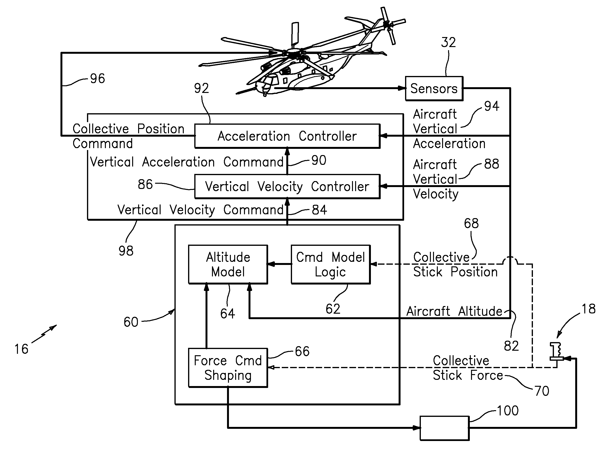
[0010]The flight control system according to the present invention includes a collective position command module for a lift axis (collective) applicable to rotary wing-aircraft with a force feedback (active) collective systems. The collective position command module, in combination with the active collective system, provides force feedback such that pilots may seamlessly command vertical speed, flight path angle or directly change collective blade pitch.
[0011]The basic premise of the collective position command module is that displacement of the collective controller commands collective blade pitch, but a constant force within a “level flight” detent commands vertical velocity or flight path angle depending on aircraft mode. Force feedback on the collective controller to provide the feeling of the “level flight” detent cues the position of an aircraft level flight state without the pilot having to refer to the instruments or make excessive collective adjustment.
[0018]Applicant has determined through piloted simulations that the present invention provides a significant increase in handling qualities, reduction in pilot workload and an increase in situation awareness. This module may alternatively be utilized for ground proximity cueing, brownout mitigation and other force feedback situations.
[0019]The present invention therefore provides force feedback as commanded by a flight control system such that pilots may seamlessly command vertical speed, flight path angle or directly change collective blade pitch.

Problems solved by technology

This piloting requirement complicates implementation of a collective controller with vertical augmentation.
This method provides limited benefit to handling qualities, since the pilot does not directly command desired aircraft state.
This method provides some additional vertical augmentation when pilot is restraining / moving collective, but overall still suffers from the drawbacks described above.
Adding this degree of freedom to the sidearm controller may also be prone to coupling which complicates single axis inputs.

Method used


Image

  • Vertical speed and flight path command module for displacement collective utilizing tactile cueing and tactile feedback
  • Vertical speed and flight path command module for displacement collective utilizing tactile cueing and tactile feedback
  • Vertical speed and flight path command module for displacement collective utilizing tactile cueing and tactile feedback

Examples


Embodiment Construction

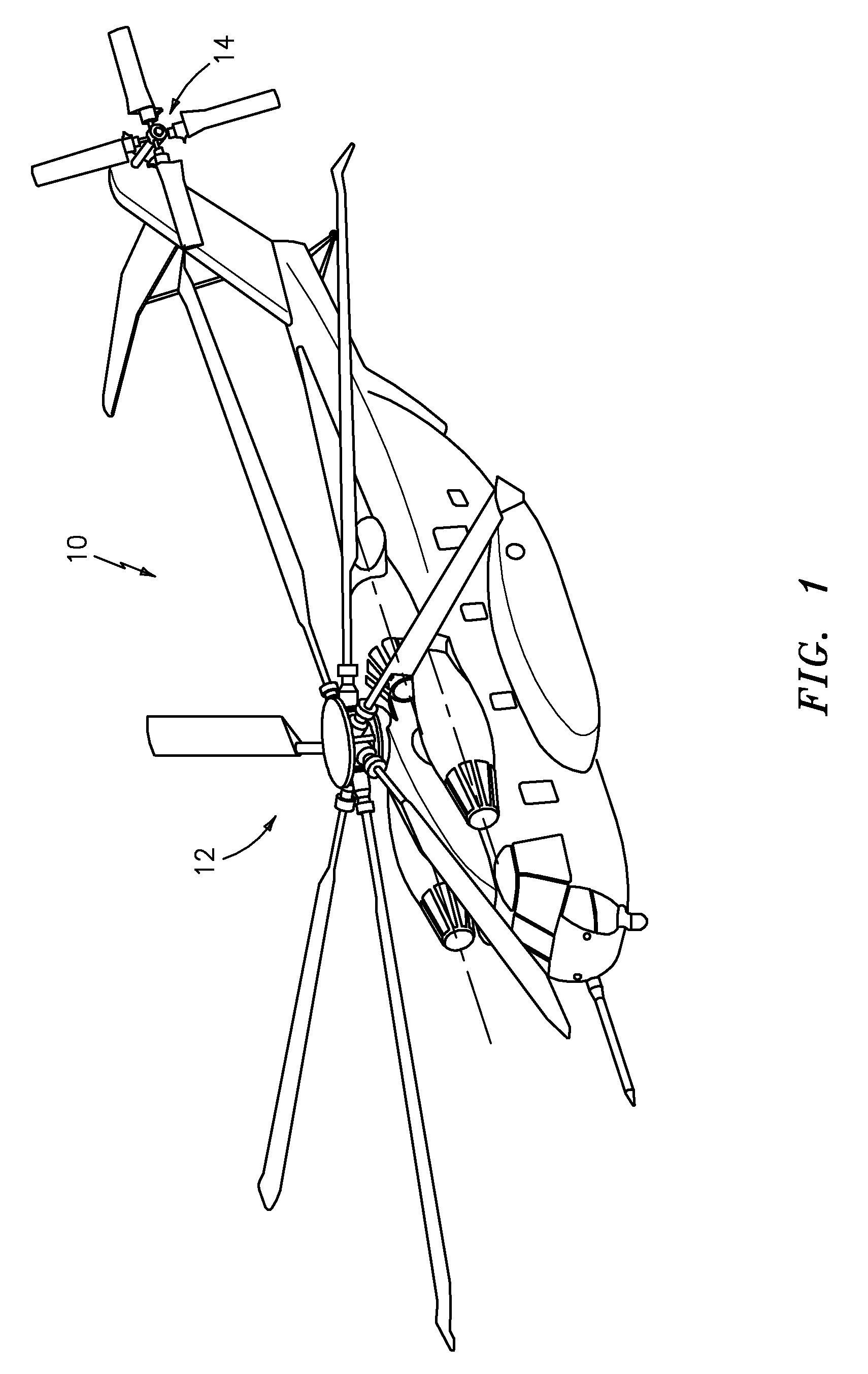
[0029]FIG. 1 illustrates a general perspective view of a helicopter embodiment 10 of a rotary wing aircraft for use with the present invention. The helicopter includes a main rotor assembly 12 and tail rotor assembly 14. Although a particular helicopter configuration is illustrated and described in the disclosed embodiment, other configurations and / or machines, such as high speed compound rotary wing aircraft with supplemental translational thrust systems, dual contra-rotating, coaxial rotor system aircraft, turbo-props, tilt-rotors and tilt-wing aircraft, will also benefit from the present invention.

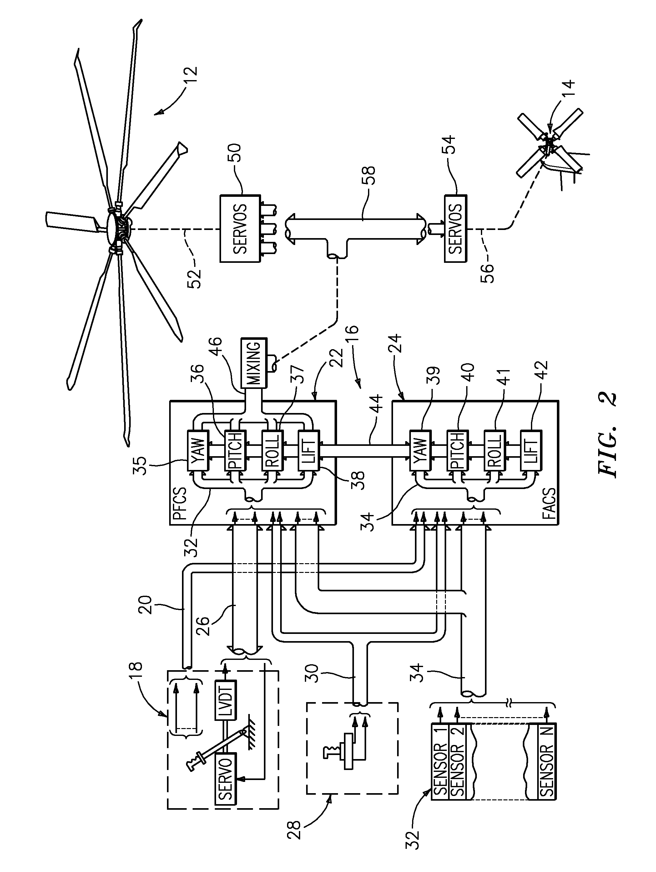
[0030]Referring to FIG. 2, the flight control system 16 includes a model following control system which shapes the pilot's controller and displacement commands through an inverse vehicle model to produce the desired aircraft response. The system includes a Primary Flight Control System (PFCS) 22 and an Flight Augmentation and Cueing System (FACS) 24. The PFCS and FACS each receive the f...


PUM


Abstract

A flight control system includes a collective position command module for a lift axis (collective pitch) which, in combination with an active collective system, provides a force feedback such that a pilot may seamlessly command vertical speed, flight path angle or directly change collective blade pitch. The collective position command module utilizes displacement of the collective controller to command direct collective blade pitch change, while a constant force application to the collective controller within a “level flight” detent commands vertical velocity or flight path angle. The “level flight” detent provides a tactile cue for collective position to reference the aircraft level flight attitude without the pilot having to refer to the instruments and without excessive collective controller movement.

Description

[0001]This invention was made with government support under Contract No.: W58RGZ-06-D-0045 awarded by the Department of the Army. The government therefore has certain rights in this invention.BACKGROUND OF THE INVENTION[0002]The present invention relates to flight control systems for rotary-wing aircraft with force feedback (active) collective systems, and more particularly to a flight control system which provides a low pilot-workload collective control system.[0003]Demand for low pilot-workload helicopters continues to increase. With the establishment of ADS-33 as the dominant handling qualities specification, the rotorcraft industry has been pursuing various methods to provide advanced flight control features. One primary method of compliance with ADS-33 is employment of a Fly-By-Wire (FBW) flight control system to decouple pilot inputs and aircraft dynamics.[0004]Several ADS-33 requirements relate to high vertical stability and precise command of vertical velocity. Unlike cyclic...

Claims


Application Information

Patent Timeline
Patent Type & Authority Patents(United States)
IPC IPC(8): G05D1/08
CPCG05D1/0607G05D1/0858B64C27/04B64C13/507
Inventor CHEREPINSKY, IGORSKAGGS, MICHAEL R.
Owner SIKORSKY AIRCRAFT CORP
Why Eureka
Eureka Blog
Learn More