
Prosthetic revision knee system

a knee replacement and knee implant technology, applied in the field of prosthetic knee replacement systems, can solve the problems of poor alignment of femoral prosthesis, lack of normal bony reference points or landmarks, and large bone loss, and achieve the effect of enlarge the intramedullary canal

Active Publication Date: 2006-10-26
GLOBUS MEDICAL INC
View PDF27 Cites 141 Cited by
  • Summary
  • Abstract
  • Description
  • Claims
  • Application Information

AI Technical Summary

Benefits of technology

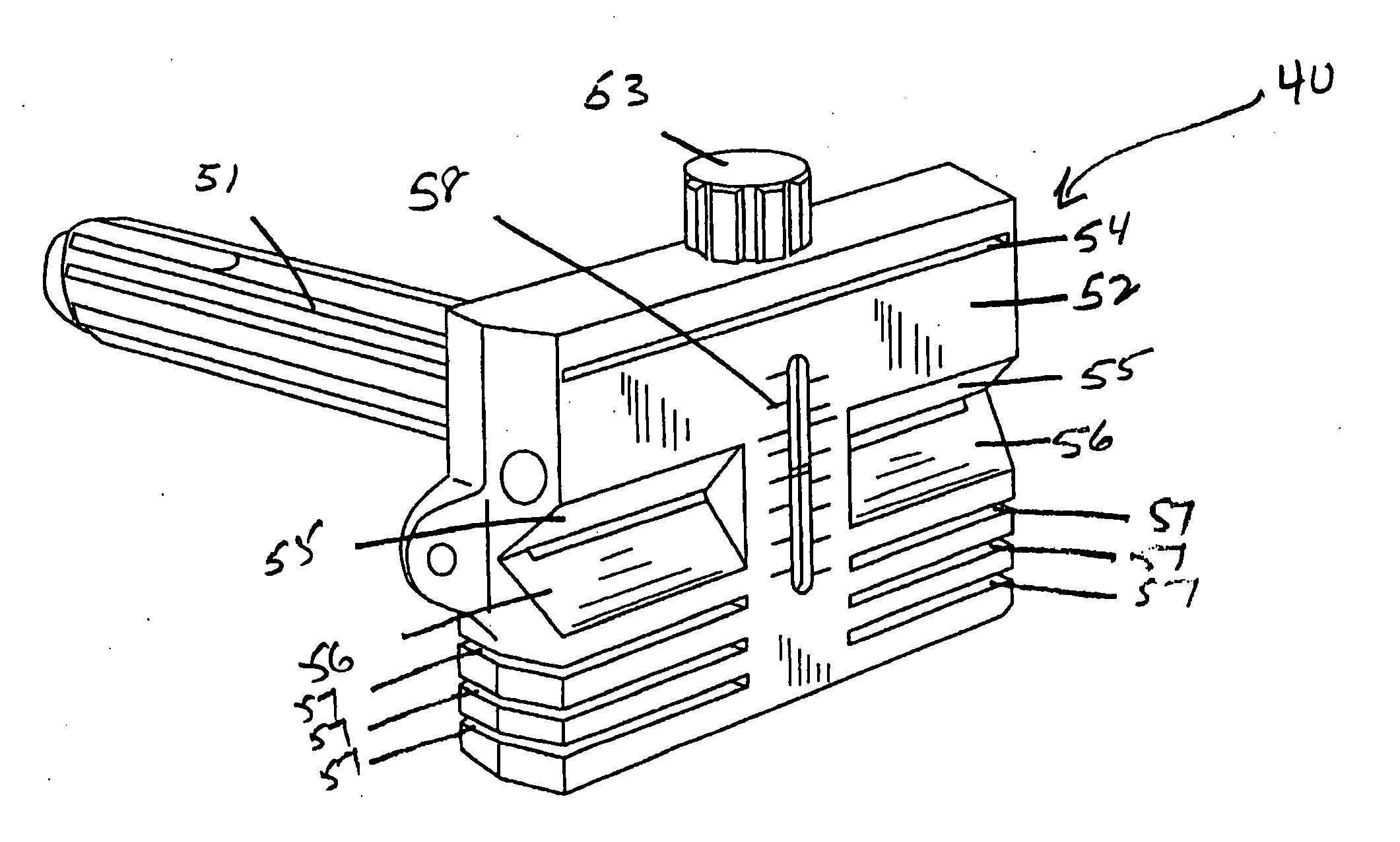
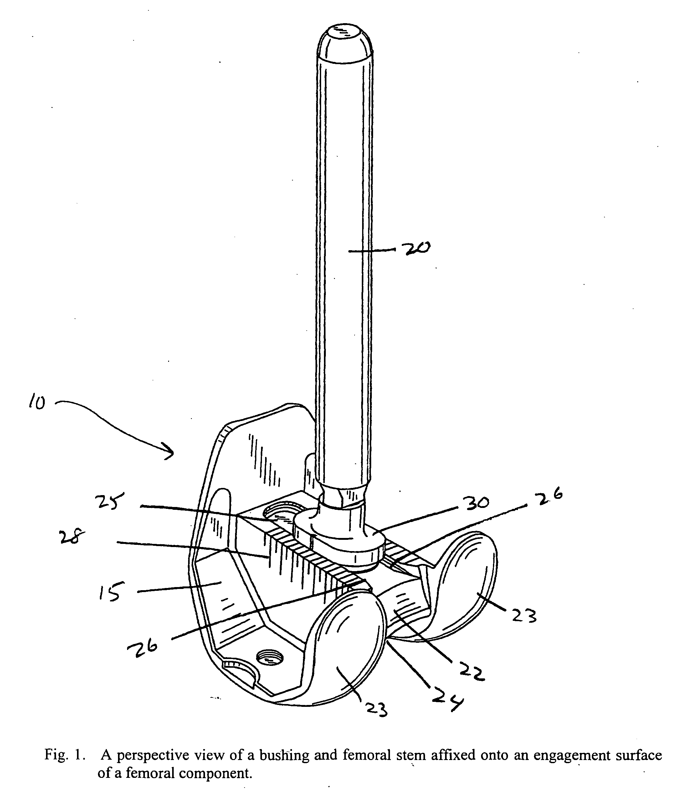
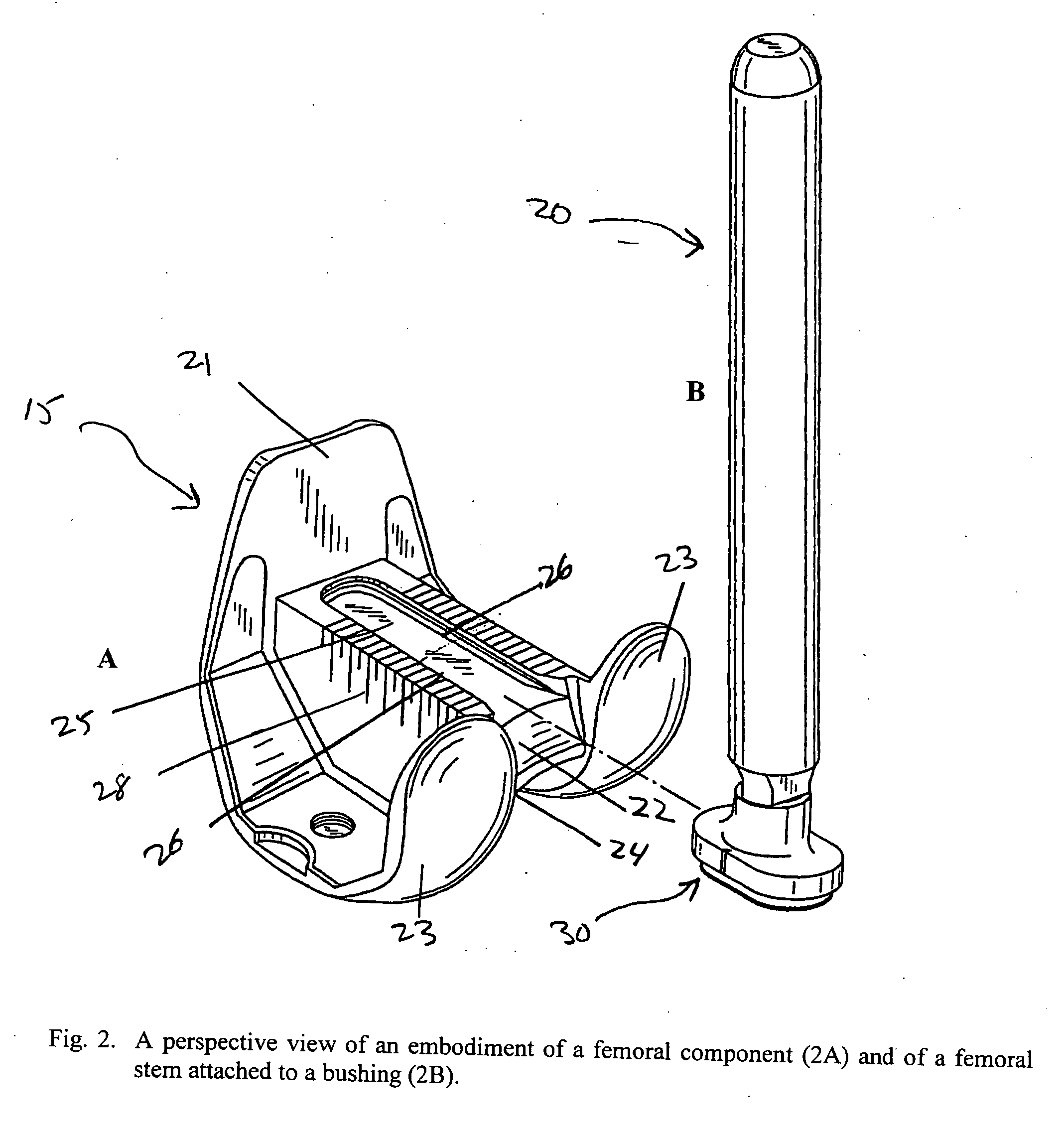
The present invention provides a method for surgically implanting an improved revision knee femoral prosthesis using an improved cutting block system for revision knee surgery in a patient. The cutting block system includes a trial stem that rotates laterally about 10 degrees around a longitudinal axis perpendicularly to the back surface of the cutting block to allow adaptability to a multitude of valgus angles. The method involves reaming the intramedullary canal of a distal femur of the patient to enlarge it, inserting the trial stem into the intramedullary canal, adjusting the cutting block to fit the femur, removing the cutting block and trial stem, affixing a bushing to the same incremental marking position of the femoral component, threadably attaching a femoral stem into the bushing, and implanting the femoral prosthesis to the distal femur of the patient. The invention also includes a femoral prosthesis comprising a femoral component having incremental markings thereon corresponding to incremental markings on the cutting block.

Problems solved by technology

In patients who require a revision knee system implant, there typically is much bone loss, and thus a lack of normal bony reference points or landmarks for properly aligning the implant.
One of the problems encountered by the surgeon is the proper orientation of the cuts so that the prosthesis will fit the femur with the correct orientation.
For example, the anterior-posterior position of the femoral stem usually is not adjustable or only adjustable in limited increments, in both cases resulting in poor alignment of the femoral prosthesis with respect to the intramedullary canal of the femur or an unbalanced flexion gap, either of which can lead to deterioration of the implant.
If the bolt loosens, it can migrate into the knee joint, resulting in injury to the surrounding tissue and damage to or interference with the prosthesis.
Additionally, such nut and bolt systems can introduce particulate matter into the knee joint which can cause infection or lead to inflammatory immune responses.

Method used


Image

  • Prosthetic revision knee system
  • Prosthetic revision knee system
  • Prosthetic revision knee system

Examples


Embodiment Construction

[0020] The present invention provides a method for implanting an improved prosthetic revision knee utilizing an improved cutting block apparatus which allows for an infinite adjustment of the anterior / posterior position of a femoral stem to suit a wide range of patient anatomies, which permits a proper alignment of the valgus angle of the femoral stem in order to accommodate the anatomical constraints of a variety of patients, and which utilizes a femoral stem locking system that will not migrate into the knee joint.

[0021]FIGS. 1 through 7 illustrate various embodiments of the prosthetic revision knee and cutting block system utilized in the method of the present invention. The method of the present invention for surgically implanting a prosthetic revision knee implant 10 in a patient is comprised of a femoral component 15 and a femoral stem 20 which, when in use, are surgically implanted to a distal femur (not shown) which has been surgically prepared to accept the implant 10 by m...


PUM


Abstract

The present invention provides a femoral component, and a method for surgical implantation of a femoral prosthesis, comprised of a revision knee implant and corresponding cutting block system. In particular, the revision knee implant, comprised of a femoral component having incremental markings thereon and a femoral stem, and corresponding cutting block system having corresponding incremental markings thereon, enables a surgeon maximally to position the cutting block adjacent as much area as possible of a distal femur of a patient and to infinitely position the femoral component in the exact position indicated by the cutting block.

Description

BACKGROUND OF THE INVENTION [0001] 1. Field of the Invention [0002] The present invention relates to revision knee implants and surgical orthopedic cutting instruments, and more particularly relates to an improved revision knee femoral prosthesis and corresponding improved cutting block apparatus for shaping a distal femur of a patient prior to implantation of the femoral prosthesis. [0003] 2. Description of Related Art [0004] The present invention relates to revision knee implants and surgical orthopedic cutting instruments, and more particularly relates to an improved revision knee femoral prosthesis and corresponding improved cutting block apparatus for shaping a distal femur of a patient prior to implantation of the femoral prosthesis. [0005] In patients who require a revision knee system implant, there typically is much bone loss, and thus a lack of normal bony reference points or landmarks for properly aligning the implant. In these cases, surgeons use the intramedullary canal...

Claims


Application Information

Patent Timeline
Patent Type & Authority Applications(United States)
IPC IPC(8): A61F5/00
CPCA61B17/155A61F2002/30604A61F2/3859
Inventor STUMPO, DAVID J.STEVENS, DONALD A.JONES, SCOTT
Owner GLOBUS MEDICAL INC
Learn More