Medical instrument, especially uterus manipulator

a technology for manipulators and medical instruments, applied in the field of medical instruments, can solve the problems of large tissue pressure, difficult to hold the actuator in a desired position, and injuries to the uterus, and achieve the effect of convenient us

Active Publication Date: 2006-10-26
KARL STORZ GMBH & CO KG
View PDF3 Cites 40 Cited by
  • Summary
  • Abstract
  • Description
  • Claims
  • Application Information

AI Technical Summary

Benefits of technology

[0008] It is, therefore, an object of the present invention to de

Problems solved by technology

Such a construction has the disadvantage that an operator needs two hands in order to lock the locking device in a desired position of the tool because the use of a screw makes it very difficult to hold the actuator in a desired position relative to the shaft and to close the locking device at the same time.
Further it

Method used


Image

  • Medical instrument, especially uterus manipulator
  • Medical instrument, especially uterus manipulator
  • Medical instrument, especially uterus manipulator

Examples


Embodiment Construction

[0042] In the following description, the expression “open position” means that the actuator is freely movable. The expression “closed position” means that the actuator is locked within the locking device.

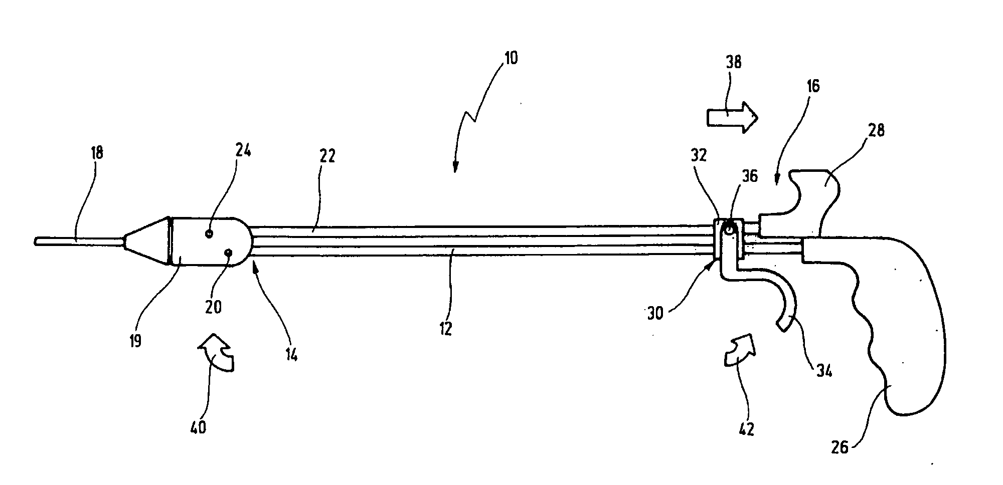
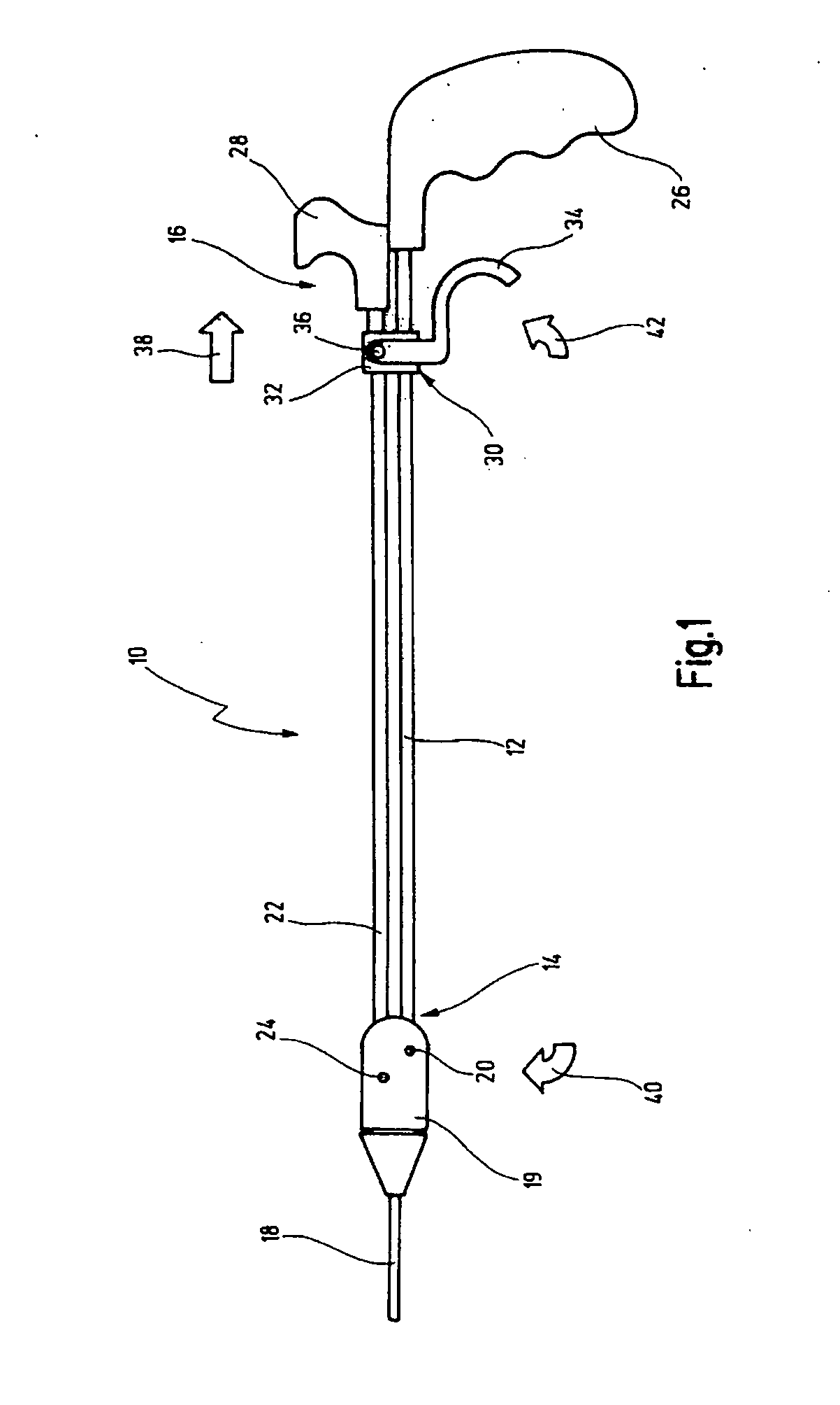
[0043] In FIG. 1, a medical instrument in the shape of a uterus manipulator is designated in its entirety with the reference numeral 10.

[0044] The uterus manipulator 10 comprises a long shaft 12 with a distal end 14 and a proximal end 16. At the distal end there is arranged a tool 18 which, for example, serves during a laparoscopic examination to move the uterus of a female patient into a desired position.

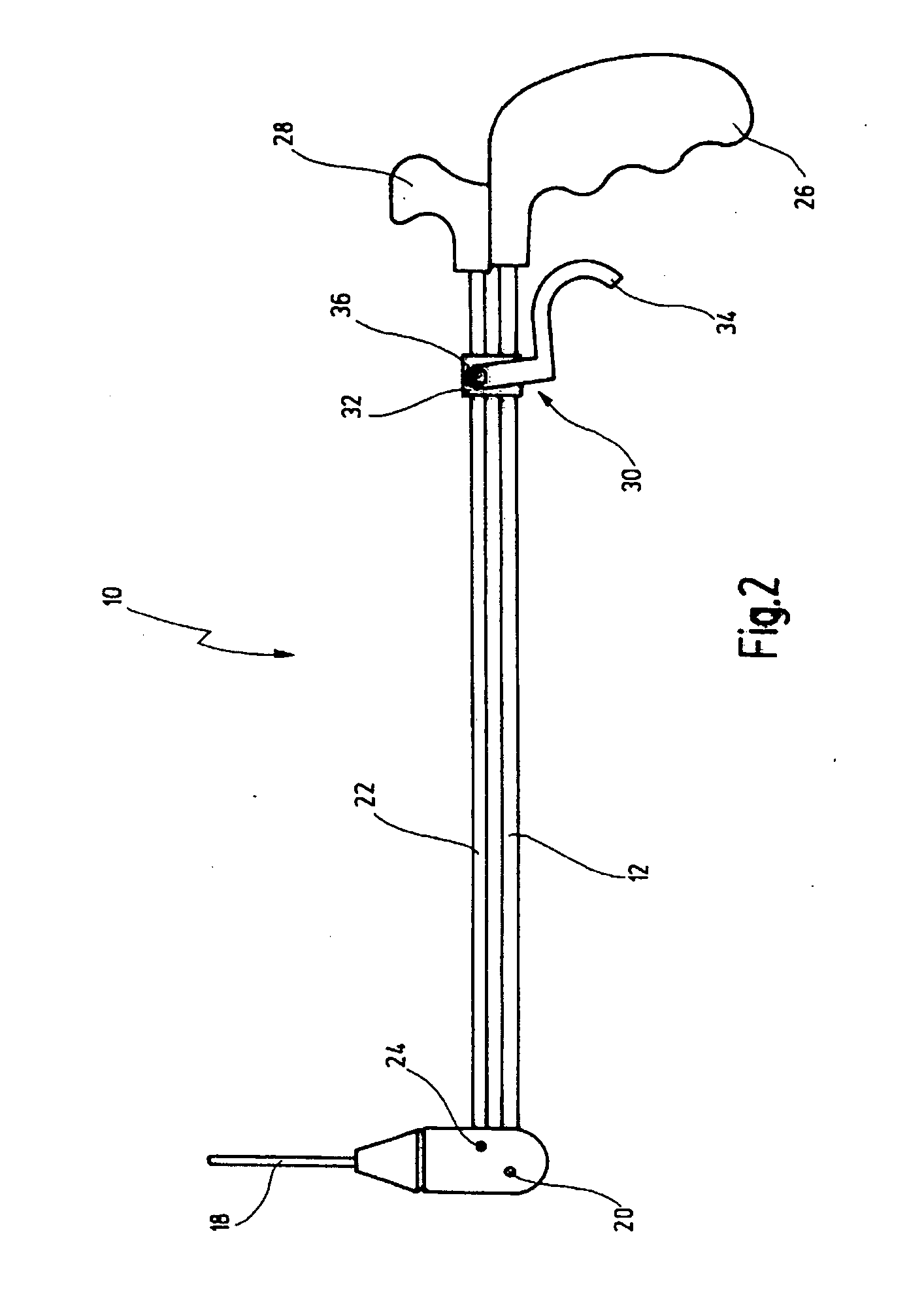
[0045] The tool 18 is connected pivotably to the shaft 12 by a bolt 20 and can be deflected relative to the shaft 12 around bolt 20. (See transition from FIG. 1 to FIG. 2)

[0046] An actuator 22 extends parallel to shaft 12 and is connected on its proximal end to a tool holder 19 via a bolt 24. By means of the actuator 22, the tool 18 can be pivoted relative to the shaft 12.

[004...


PUM


Abstract

A medical instrument, especially a uterus manipulator, comprises a shaft, an actuator movable relative to said shaft in order to move a tool and a locking device to lock the actuator relative to the shaft. It is now proposed that the locking device comprises a clamping element which is slidably arranged therein.

Description

FIELD OF THE INVENTION [0001] The present invention relates to a medical instrument comprising a shaft having a distal and a proximal end, a tool at the distal end of the shaft, a grip at the proximal end of the shaft, an actuator with which the tool is movable, and a locking device comprising a handle and a clamping element, the clamping element being movable by the handle between a first and a second position, whereby in the first position of the clamping element the actuator is freely movable, and in the second position of the clamping element the actuator is locked in the locking device. [0002] Such a medical instrument is, for example, a uterus manipulator. [0003] A uterus manipulator is used among other things to move the uterus to a desired position during laparoscopic examinations in the abdomen of a female patient. This is done, for example, in order to examine a concealed part of the uterus or to move the uterus out of an area which is to be examined or treated by laparosc...

Claims


Application Information

Patent Timeline
IPC IPC(8): A61B17/42
CPCA61B2017/2927A61B17/4241
Inventor DOLL, FRANKHAHN, MARTIN
Owner KARL STORZ GMBH & CO KG
Why Eureka
Try Eureka