
Flush valve cleaner dispenser system

Inactive Publication Date: 2006-11-02
FLUIDMASTER
View PDF38 Cites 12 Cited by
  • Summary
  • Abstract
  • Description
  • Claims
  • Application Information

AI Technical Summary

Benefits of technology

[0022] In summary, a toilet cleaner dispenser system is centered above an overflow tube and configured to deliver cleanser solution directly to the overflow tube without a hose. A disposable cartridge containing a cleanser tablet is removably coupled to a dispenser housing. Refill water is directed to the housing through an inlet and brought into contact with the cleanser tablet to form a cleanser solution. The cleanser solution exits an outlet of the housing into a receptacle which directs the solution downwardly and directly into the overflow tube. Inlet and outlet water traps prevent fumes from escaping the housing.

Problems solved by technology

Since conventional dispensers are often purchased as an add-on, after-market product, some common drawbacks are associated with prior art dispensers.
Cleaning agents, such as tablets, which dissolve into the refill water upon contact often generate harmful fumes that can damage the interior components of the toilet tank.
The need to prevent the escape of fumes has led to awkward and bulky structures that also cause the entire dispenser unit to take up the limited space within the toilet tank.
Accordingly, certain dispenser units in the prior art do not enable the lid to close on a standard toilet tank, thereby creating a rocking or tilted appearance which is undesirable.
Hoses can come loose, thereby dumping harmful chemicals into the toilet tank without the awareness of the consumer.

Method used


Image

  • Flush valve cleaner dispenser system
  • Flush valve cleaner dispenser system
  • Flush valve cleaner dispenser system

Examples


Embodiment Construction

[0031] The invention and its various embodiments can now be better understood by turning to the following detailed description wherein illustrated embodiments are described. It is to be expressly understood that the illustrated embodiments are set forth as examples and not by way of limitations on the invention as ultimately defined in the claims.

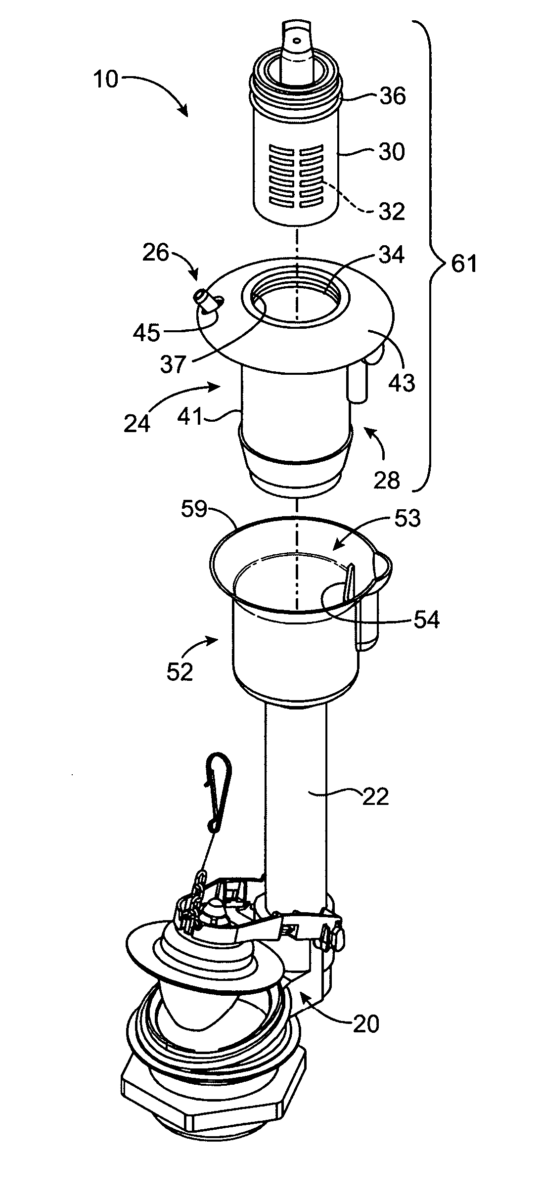
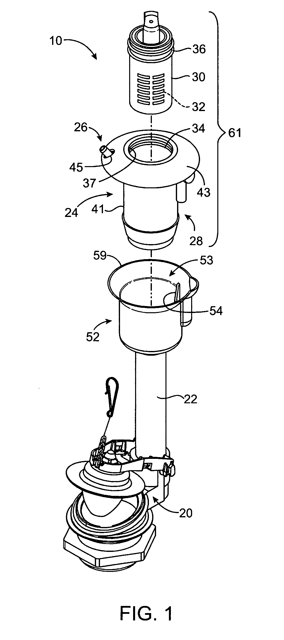
[0032]FIG. 1 is an exploded, perspective view of a toilet cleaner dispenser system 10. The system 10 may comprise a flush valve 20 having an overflow tube 22. Alternatively, the system 10 may comprise a unit that is configured to be coupled to an existing overflow tube A coupling joint may be employed to couple the system 10 an overflow tube, thereby allowing the manufacture of various overflow tube heights.

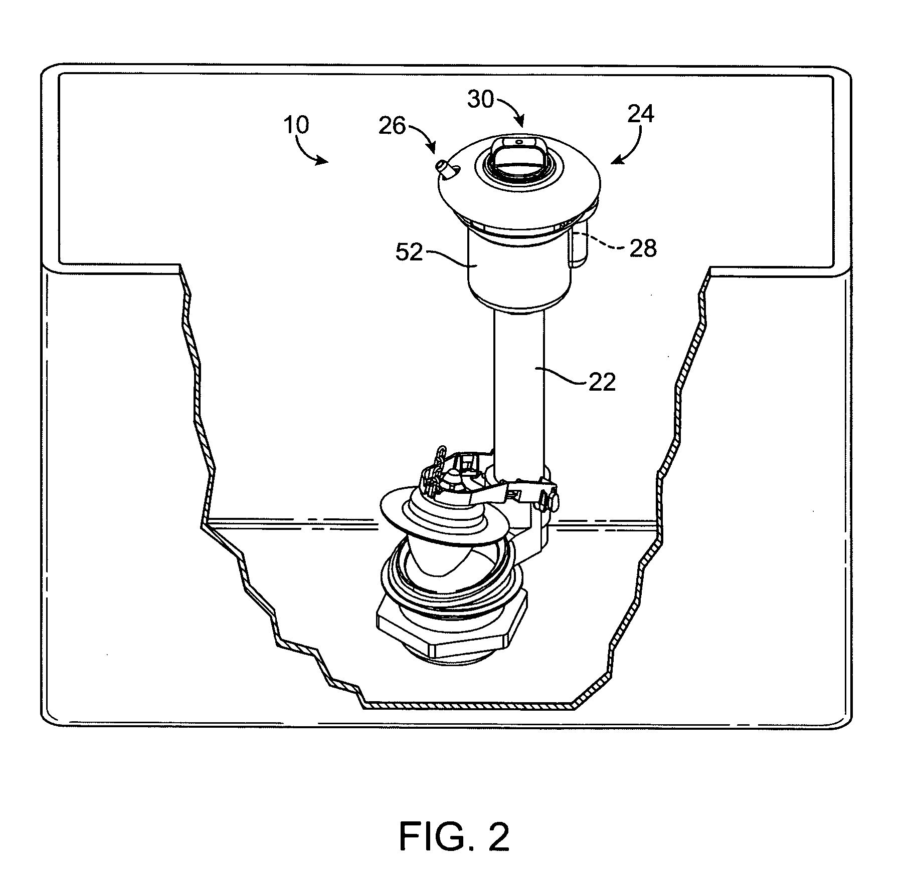
[0033] In FIGS. 1 and 2, the dispenser system 10 comprises a dispenser housing 24. The dispenser housing 24 includes an inlet 26 and an outlet 28. In the preferred embodiment, the inlet 26 is upwardly facing while the outlet 28 is gene...


PUM


Abstract

A toilet cleaner dispenser system is centered above an overflow tube and configured to deliver cleanser solution directly to the overflow tube without a hose. A disposable cartridge containing a cleanser tablet is removably coupled to a dispenser housing. Refill water is directed to the housing through an inlet and brought into contact with the cleanser tablet to form a cleanser solution. The cleanser solution exits an outlet of the housing into a receptacle which directs the solution downwardly and directly into the overflow tube. Inlet and outlet water traps prevent fumes from escaping the housing.

Description

RELATED APPLICATIONS [0001] This application relates to, claims priority from, and incorporates herein by reference, as if fully set forth, U.S. Provisional Patent Application Ser. No. 60 / 675,529 filed on Apr. 27, 2005 and entitled “INTEGRATED CLEANER DISPENSER WITH FLUSH VALVE”.BACKGROUND OF THE INVENTION [0002] 1. Field of the Invention [0003] The present invention relates generally to cleaner dispenser systems for toilets. [0004] 2. Description of Prior Art and Related Information [0005] Cleaning dispenser systems for toilets are commonly located in the toilet tank. Since conventional dispensers are often purchased as an add-on, after-market product, some common drawbacks are associated with prior art dispensers. [0006] For example, dispensers typically include clips in order to fasten the dispenser to the wall of the toilet tank. These clips often get in the way of the toilet lid being able to fully close on the toilet tank. [0007] Cleaning agents, such as tablets, which dissolv...

Claims


Application Information

Patent Timeline
IPC IPC(8): E03D9/02
CPCE03D9/037
Inventor COPPOCK, CHRISTOPHER A.
Owner FLUIDMASTER
Learn More