Laminate molding method and laminate molding apparatus

a technology of laminate molding and laminate, which is applied in the direction of additive manufacturing apparatus, process efficiency improvement, additive manufacturing, etc., can solve the problems of minute structures cannot be formed in molded objects, and adversely affecting the quality of molded objects, etc., to achieve the effect of restricting fumes

Pending Publication Date: 2021-12-23
TOYOTA JIDOSHA KK
View PDF4 Cites 3 Cited by
  • Summary
  • Abstract
  • Description
  • Claims
  • Application Information

AI Technical Summary

Benefits of technology

[0005]On that account, the inventors of the present disclosure conceived that the remains of the fumes were restrained by increasing the flow rate of the gas. However, when the flow rate of the gas is increased, particles with small diameters are carried away while particles with large diameters remain. This causes such a problem that a minute structure cannot be formed in a molded object.
[0029]The present disclosure can restrain fumes from adversely affecting a molded object.

Problems solved by technology

However, the fumes might remain and adversely affect the quality of a molded object.
This causes such a problem that a minute structure cannot be formed in a molded object.
In a case where the flow amount of the gas GF91 is not sufficient, the fume F9 might remain and adversely affect the quality of a molded object.

Method used


Image

  • Laminate molding method and laminate molding apparatus
  • Laminate molding method and laminate molding apparatus
  • Laminate molding method and laminate molding apparatus

Examples


embodiment 1

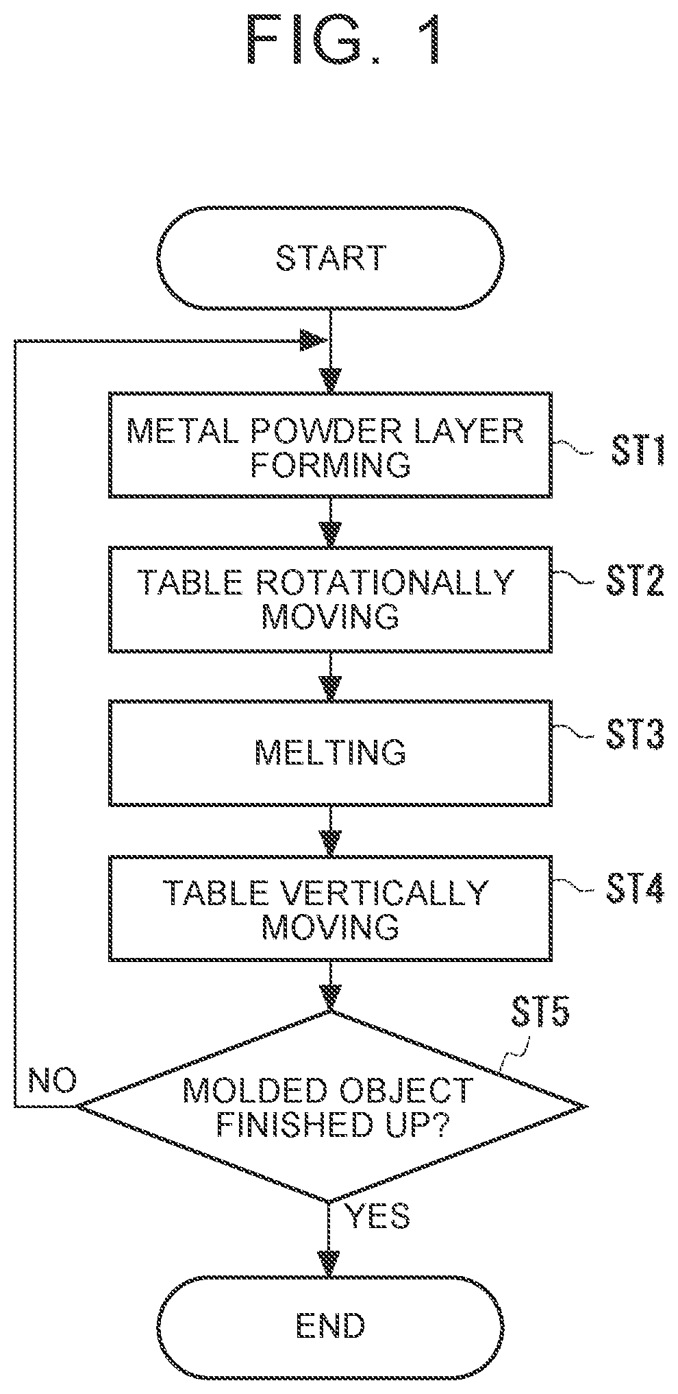
[0047]With reference to FIG. 1, a laminate molding method according to Embodiment 1 will be described. FIG. 1 is a flowchart illustrating a laminate molding method according to Embodiment 1.

[0048]Metal powder is supplied onto a table, so that a metal powder layer is formed (metal powder layer forming step ST1). The metal powder can be supplied onto the table by use of a squeegee, a net, and the like, for example.

[0049]Subsequently, an electromagnetic energy source and the table are rotated relative to each other (table rotationally moving step ST2). More specifically, due to this rotation, the metal powder layer moves from a first region on a main surface of the table on which the metal powder layer is formed in the metal powder layer forming step ST1 to a second region on the main surface of the table below the laser head.

[0050]Subsequently, electromagnetic energy emitted from the electromagnetic energy source is applied to the metal powder layer, so that the metal powder layer is ...


PUM

PropertyMeasurementUnit
particle diameteraaaaaaaaaa
electromagnetic energyaaaaaaaaaa
timeaaaaaaaaaa

Abstract

Provided is a laminate molding method for additionally manufacturing a molded object on a table by use of metal powder. The laminate molding method includes: a metal powder layer forming step of forming a metal powder layer by supplying metal powder onto a table; a melting step of melting the metal powder layer by applying, to the metal powder layer, electromagnetic energy emitted from an electromagnetic energy source; a rotating step of rotating the electromagnetic energy source and the table relative to each other; and a table vertically moving step of vertically moving the table relative to the electromagnetic energy source. Gas is emitted from a gas emission port toward an outer side of the table, the gas emission portion being provided in generally a center of the table.

Description

CROSS-REFERENCE TO RELATED APPLICATION[0001]This application claims priority to Japanese Patent Application No. 2020-104993 filed on Jun. 18, 2020, incorporated herein by reference in its entirety.BACKGROUND1. Technical Field[0002]The present disclosure relates to a laminate molding method and a laminate molding apparatus and particularly relates to a laminate molding method and a laminate molding apparatus each for manufacturing a molded object by use of powder.2. Description of Related Art[0003]One example of such a laminate molding apparatus is described in Japanese Unexamined Patent Application Publication (Translation of PCT Application) No. 2005-534543 (JP 2005-534543 A). In the laminate molding apparatus, a formation region in which a molded object is to be formed is displaced rotatably relative to a material application device configured to form a layer of a structural material by application, and a solidification device. Hereby, the material application device and the solid...

Claims


Application Information

Patent Timeline
Patent Type & Authority Applications(United States)
IPC IPC(8): B22F10/20B33Y30/00B33Y70/00B22F12/00B22F12/41
CPCB22F10/20B33Y30/00B33Y70/00B33Y10/00B22F12/41B22F2202/06B22F2999/00B22F12/226B33Y40/00B22F12/37B22F10/28B22F12/70B22F10/322B33Y50/02Y02P10/25B22F10/30B22F12/222B22F12/67
Inventor ZHANG, SHUAI
Owner TOYOTA JIDOSHA KK
Why Eureka
Try Eureka