

Copper pipe producing cooling device
A cooling device and copper tube technology, applied in the field of copper tube production cooling devices, can solve the problems of easy heating and heating, threatening production safety, environmental pollution, etc., and achieve the effects of avoiding oil fume, good cooling effect, and improving workshop environment
- Summary
- Abstract
- Description
- Claims
- Application Information
AI Technical Summary
Problems solved by technology
Method used
Image

Examples
Embodiment Construction
[0017] The technical solution of the present invention will be further described below in conjunction with the accompanying drawings.
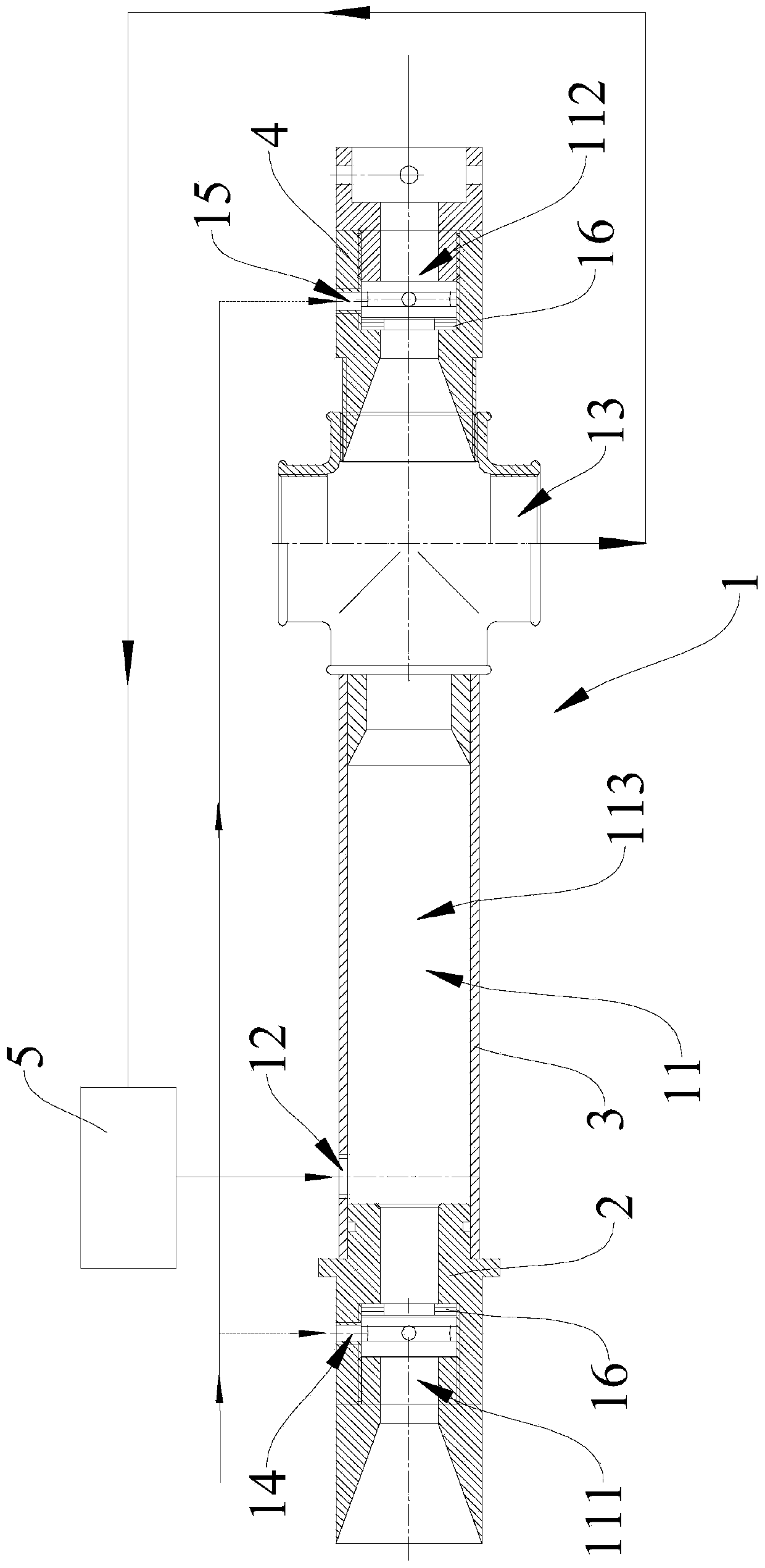
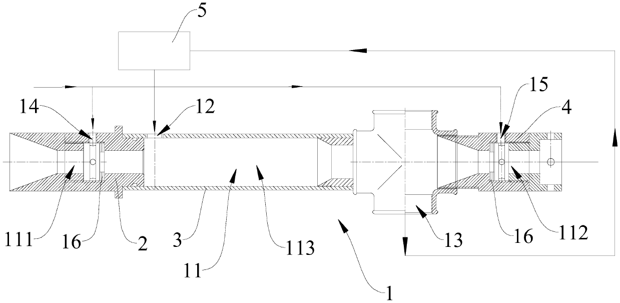
[0018] see figure 1 As shown, the copper pipe production cooling device includes a cooling pipe body 1, and the cooling pipe body has a cooling through hole 11 for the copper pipe to penetrate. The first air-cooled section 111 and the second air-cooled section 112, the peripheral side of the cooling pipe body 1 is provided with a liquid inlet 12 for the cooling liquid to enter the liquid-cooled section 113, and for the cooling liquid in the liquid-cooled section 113 to flow out The liquid outlet 13, the peripheral side of the cooling pipe body 1 is also provided with a first air inlet 14 that makes the first air-cooled section 111 communicate with the outside world, and a second air inlet that makes the second air-cooled section 112 communicate with the outside world 15. Both the first air inlet 14 and the second air inlet 15 are connected wi...
PUM
 Abstract
Description
Claims
Application Information