Multi-plate clutch

a multi-plate clutch and clutch technology, applied in the field of multi-plate clutches, can solve the problems of engine output undergoing a brief acceleration and deceleration, noise and vibration, engine wear and tear of its component parts, etc., to reduce noise generation, less rotational play, and extend service life

Inactive Publication Date: 2006-11-02
LEWIS LEIF
View PDF21 Cites 9 Cited by
  • Summary
  • Abstract
  • Description
  • Claims
  • Application Information

AI Technical Summary

Benefits of technology

[0010] The present invention overcomes the shortcomings of previously known multi-plate clutches wherein the improved clutch configuration serves to substantially extend service life and to reduce the generation of noise during its operation. Such gains are realizable in dry as well as wet type applications.
[0011] The present invention generally provides for the differentiation of the rotational coupling of one of the drive plates of a multi-plate clutch to the shell or basket so as to have less rotational play than the other drive plates in the clutch pack. By limiting the rotational play of just one plate, the ability of the individual plates to shift axially as is required for the plates to disengage is preserved, while limiting the rotational play of such one plate greatly reduces the rotational play of all of the other plates when the plates are fully engaged.
[0012] In a preferred embodiment of the present invention, the multi-plate clutch includes a stack of drive plates and driven plates that are disposed in a conventional configuration to the extent that they are arranged in an alternating sequence along a common axis wherein one set of plates is keyed to an internally disposed shaft or carrier and the other set of plates is keyed to an externally disposed shell. Each of the plates that is keyed to the externally disposed shell includes a series of keys or tabs that extend radially therefrom and that are configured for receipt in axially extending channels that are formed along the interior surface of the shell. In accordance with the invention, one of the plates that is keyed to the externally disposed shell is similarly configured but differentiated in terms of its dimensions. Such dimensioning has a stabilizing influence on the positions and movements of the other plates while the stack of plates is under compression to thereby greatly reduce the force of the impacts of the keys against the channel walls.
[0013] The “stabilizer” plate of the present invention is differentiated from the other plates that are keyed to the externally disposed shell in that the dimensions of its keys are selected to much more closely coincide with the dimensions of the channel that is formed in the interior surface of the shell, i.e. with less rotational play, while the keys of all of the other plates are dimensioned to have a substantially looser fit, i.e. more rotational play within the channels as per conventional multi-plate clutch configurations. The unexpected result achieved by the present invention is that while the inclusion of one such stabilizer plate in the stack of drive plates achieves the desired rotational stability, it does not adversely affect the operation of the clutch. The stabilizing plate can be included anywhere in the sequence of plates but is most preferably positioned at either extreme end of the stack.
[0014] Upon compression of the stack of drive plates and driven plates, the stabilizer plate serves to stabilize the rotational position of all of the other plates in the stack relative to the channels in the shell. The minimal play between the keys of the stabilizer plate and the channels in which they are received substantially precludes relative rotation between the stabilizer plate and the shell. Because all of the other plates are frictionally linked to the stabilizer plate, any rotation relative to the stabilizer plate and therefore relative to the channels in the shell requires that such friction be overcome. Overcoming the friction requires a substantial amount of force which in turn greatly reduces the relative rotational velocity that can be achieved. The much reduced relative rotational velocity in turn greatly reduces the force with which the keys engage the sidewalls of the respective channels. This substantially reduces wear to the engaging surfaces and all but eliminates the generation of a hammering noise. The stabilizer plate may optionally be dimensioned to have a thickness greater than the thickness of the other drive plates in order to increase the surface area of each of the keys that contacts the sidewalls of the channels and thereby reduce wear to both the keys as well as the channel sidewalls.

Problems solved by technology

There are however some disadvantages associated with multi-plate clutch devices, including the propensity for the accelerated wear of its component parts and the noise that is caused by the interaction of the wearing parts.
While this achieves the intended effect, it is the underlying cause of a number of shortcomings inherent in multi-plate clutches.
This becomes especially problematic in automotive and motorcycle applications as such impacts will occur with every upshift and downshift, with every switch between accelerative loading and decelerative loading while in a gear and even when in neutral, as each firing pulse will cause the engine's output to undergo a brief acceleration and deceleration.
These impacts not only generate noise and vibration, but cause the keys and / or channels to wear.
Any such wear accelerates the rate of further wear along with a commensurate increase in noise and vibration as the impacts become harsher until the clutch becomes unserviceable.
Reducing the tolerances between the keys and channels has generally been found to be of limited utility as the function of the clutch quickly becomes compromised.
Close tolerances between the keys of each of the plates and the corresponding channels renders the keys prone to binding or jamming in the channels should the plates and / or associated keys become distorted, angled or otherwise misaligned.
Such binding or jamming would prevent or delay the clutch from decoupling the driving and driven components when the compressive force is released thereby making it difficult to select neutral or shift gears.
However, the oil used in so-called “wet” clutches introduces a significant amount of drag to thereby rob power and increase fuel consumption.
Additionally, in four stroke motorcycle applications, such clutches tend to contaminate the engine oil.
While such modifications have been found to be somewhat effective in reducing the impact loads and the associated noise and damage, the added components not only add complexity to the clutch mechanism but are more prone to failure.
Damaged or broken metallic parts that come loose can cause further damage to the clutch and difficulty in its operation while broken O-rings can prevent plates from separating and shaking apart.

Method used


Image

  • Multi-plate clutch
  • Multi-plate clutch
  • Multi-plate clutch

Examples


Embodiment Construction

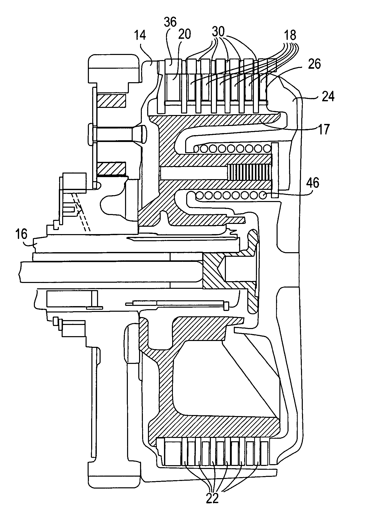
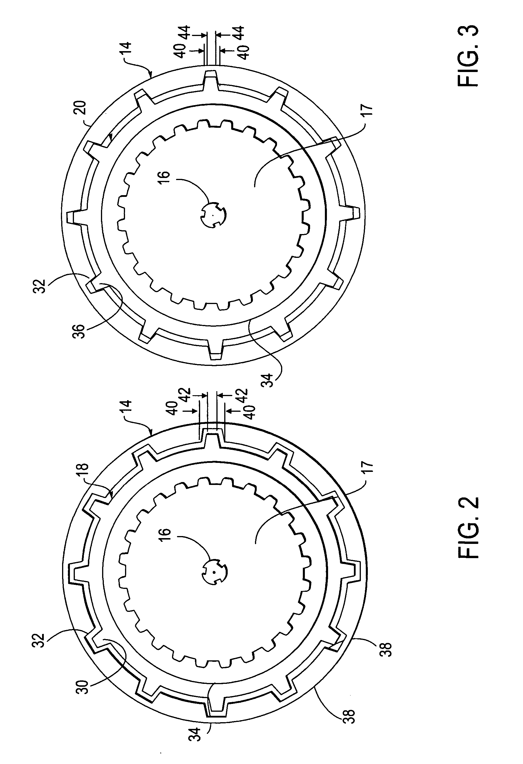
[0023] The multi-plate clutch of the present invention overcomes many of the shortcomings of previously known multi-plate clutch configurations to provide longer service life and quieter operation. The inclusion of a specially dimensioned drive plate, referred to herein as a stabilizer plate, in combination with conventional drive plates serves to rotationally stabilize the entire clutch pack without impeding the clutching and declutching operations. By stabilizing the relative rotational movements of interacting components, the force of the impacts between the engaging surfaces of such components is greatly reduced to yield a commensurate reduction in damage and wear that would otherwise invariably result with use. The reduction in impact forces additionally serves to reduce the hammering noise that would otherwise be generated.

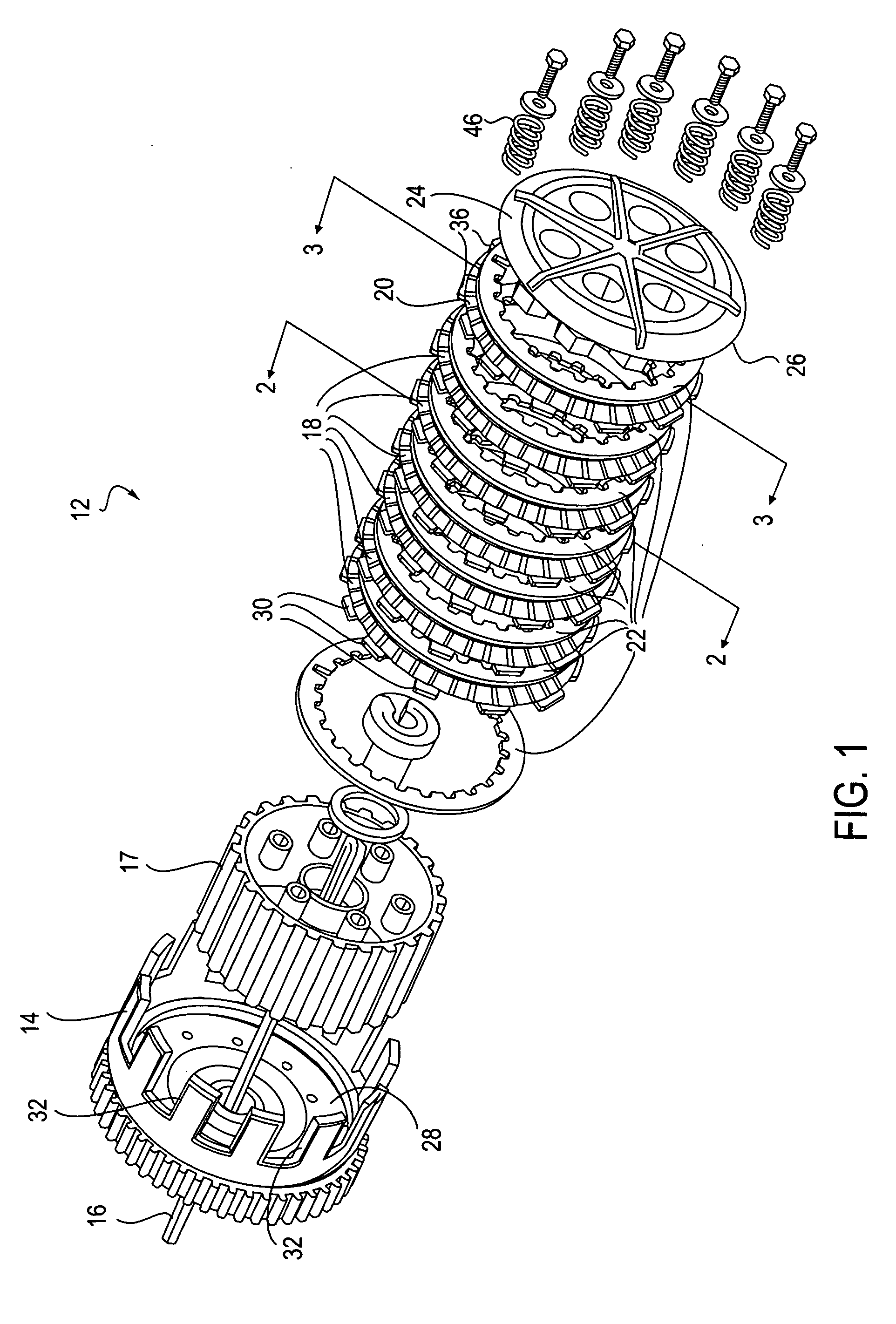
[0024]FIG. 1 is an exploded perspective view of a preferred embodiment of the present invention. The multi-clutch 12 serves to interruptably transfer torqu...


PUM


Abstract

A multi-plate clutch includes a plurality of friction plates that are rotationally coupled to a concentric shell wherein keys radially extending from each friction plate are slidably received in axial channels formed in the interior surface of the shell. The keys of all but one of the friction plates are dimensioned to have a relatively loose fit in the channels while the keys on a single friction plate are dimensioned to have a substantially tighter fit in the channels. This has a stabilizing effect on the entire stack without impeding the operation of the clutch. Rotational stabilization of the plates serves to dampen the impact of the edge of each of the keys of each of the plates against the channel sidewall during abrupt load changes in the drivetrain to thereby reduce wear and the generation of noise.

Description

BACKGROUND OF THE INVENTION [0001] The present invention generally relates to multi-plate clutches and more particularly pertains to the extension of the service life of such devices as well as the reduction of the noise that is typically generated thereby. [0002] Clutches are employed for interruptably coupling two rotating components to one another such as for example an engine to a transmission. A multi-plate clutch configuration offers significant advantages over a single-plate clutch configuration including the ability to accommodate a greater torque handling capability in an overall smaller package. As a consequence, such clutch configurations are found in a large variety of different applications including high-performance motorcycles and automobiles, trucks and heavy machinery. There are however some disadvantages associated with multi-plate clutch devices, including the propensity for the accelerated wear of its component parts and the noise that is caused by the interactio...

Claims


Application Information

Patent Timeline
Patent Type & Authority Applications(United States)
IPC IPC(8): F16D13/52
CPCF16D13/52F16D13/683F16D13/56
Inventor LEWIS, LEIF
Owner LEWIS LEIF
Why Eureka
Try Eureka