

Multi-level optical writer
- Summary
- Abstract
- Description
- Claims
- Application Information
AI Technical Summary
Benefits of technology
Problems solved by technology
Method used
Image

Examples
first embodiment
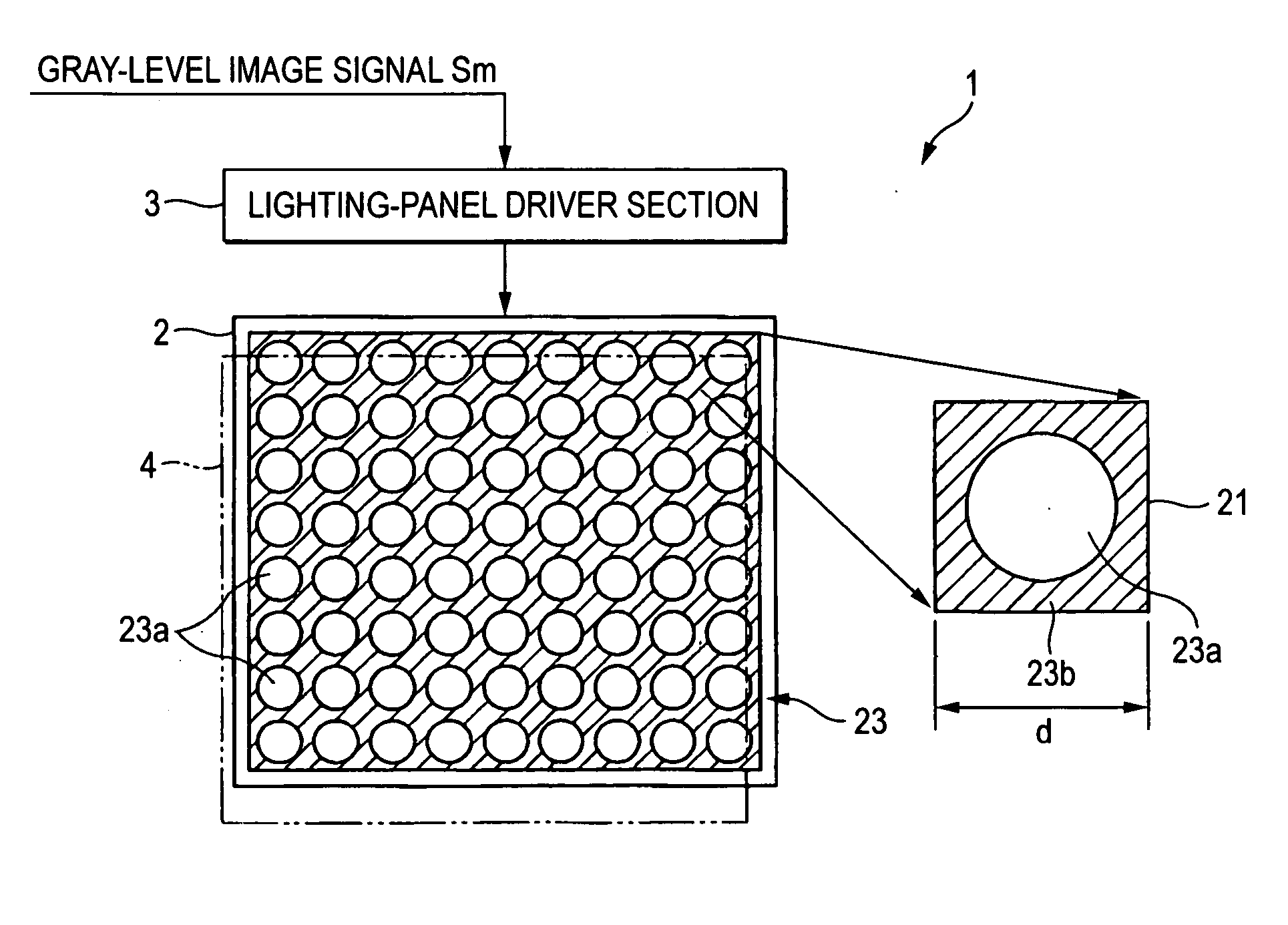
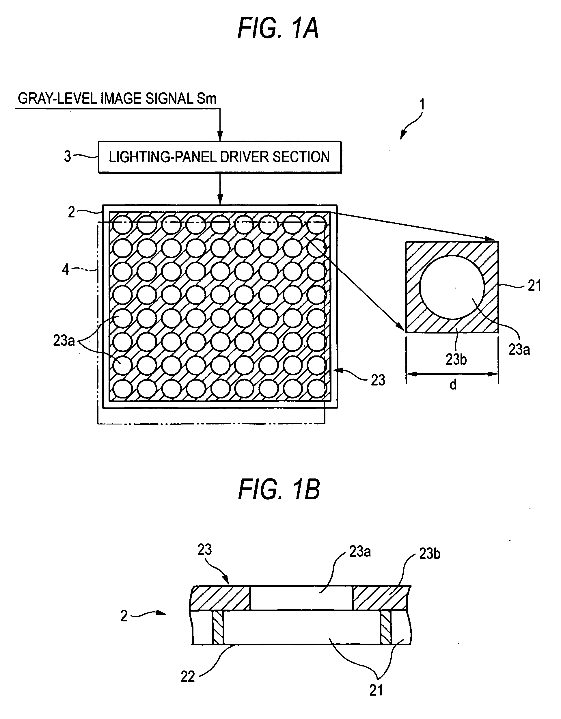
[0045]FIGS. 1A and 1B show a multi-level optical writer according to the present invention. A multi-level optical writer 1 has an lighting panel 2 as a light illuminator placed oppositely to an optical-write-type display recording medium (hereinafter, referred to as a “display recording medium”) and arranged with a plurality of pixels 21 two-dimensionally, and an lighting-panel drive section-3 as a signal generating section for controlling the emission-light levels on the pixels of the lighting panel 2 according to a gray-level image signal Sm sent from a not-shown control section. Incidentally, a write section is constituted by the lighting panel 2 and the lighting-panel drive section 3.
[0046] The lighting panel 2 has an LCD (liquid-crystal display) panel and a backlight arranged at backside of the LCD panel and for emitting white light or the like. Note that the lighting panel 2 may employ another structure, e.g. an ELD (electroluminescence display).
[0047] Meanwhile, in the light...
second embodiment
[0058] Accordingly, when lighting is made based on such multi-level input image data 200 as shown in FIG. 5A, the writing to the display recording medium 144 by the conventional lighting panel 141 provides a binary display with a black print region 147 and a white print region 148, as shown in FIG. 5D. On the contrary, with the lighting panel 2 the optical dots 45, in a black print region 24, are identical in size similarly to the conventional black print region 147. However, in a white print region 25, lighting is such that on-pixel light amount is different from row to row to thereby make the optical dots 45 different in size. Due to this, multi-level display is obtained.
[0059] According to the second embodiment, a multi-level image can be stably formed on the display recording medium 4 having a binary γ-characteristic (gray-level characteristic) by the simple structure, similarly to the first embodiment.
[0060]FIG. 6 shows a multi-level optical writer according a third embodimen...
seventh embodiment
[0065] A light restriction member 23 in a seventh embodiment is based on a concentration filter having a light transmissivity continuously decreasing in a direction from the center toward the outer, as shown in FIG. 8A.
PUM
 Abstract
Description
Claims
Application Information