Multi-stage scanning method for increasing scanning speed and enhancing image quality

a scanning speed and multi-stage technology, applied in the field of multi-stage scanning methods for increasing scanning speed and enhancing image quality, can solve the problems of insufficient accelerating distance, high cost, and more difficult to accelerate optical modules b>10/b>, so as to increase scanning speed and image quality, and improve image quality. , the effect of increasing scanning speed

Active Publication Date: 2006-11-02
AVISION
View PDF18 Cites 3 Cited by
  • Summary
  • Abstract
  • Description
  • Claims
  • Application Information

AI Technical Summary

Benefits of technology

[0018] It is therefore an object of the invention to provide a multi-stage scanning method for increasing a scanning speed and enhancing an image quality, wherein the higher scanning speed and image quality may be obtained by lengthening an accelerating distance of an optical module in a scanner.
[0019] To achieve the above-identified object, the invention provides a multi-stage scanning method for increasing a scanning speed and enhancing an image quality. The method includes the steps of: moving an optical module, in a forward direction, from a start position to a forward-internal position, and then enabling the optical module to scan a first portion of a document to obtain a first image until the optical module reaches a forward-boundary position; moving the optical module, in the forward direction, from the forward-boundary position to an end position and then stopping the optical module; moving the optical module, in a reverse direction which is reverse to the forward direction, from the end position to a reverse-internal position, and then enabling the optical module to scan a second portion of the document to obtain a second image until the optical module reaches a reverse-boundary position, wherein the forward-boundary position and the reverse-boundary position define a scan range of the document along the forward direction and the reverse d...

Problems solved by technology

However, it is more difficult to accelerate the optical module 10 to the speed V if the distance from the position P6 to the position PS is shorter.
In this condition, a motor with a larger output torsio...

Method used


Image

  • Multi-stage scanning method for increasing scanning speed and enhancing image quality
  • Multi-stage scanning method for increasing scanning speed and enhancing image quality
  • Multi-stage scanning method for increasing scanning speed and enhancing image quality

Examples


first embodiment

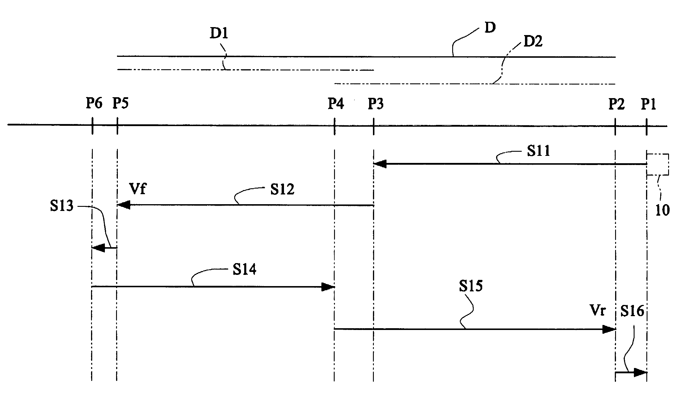
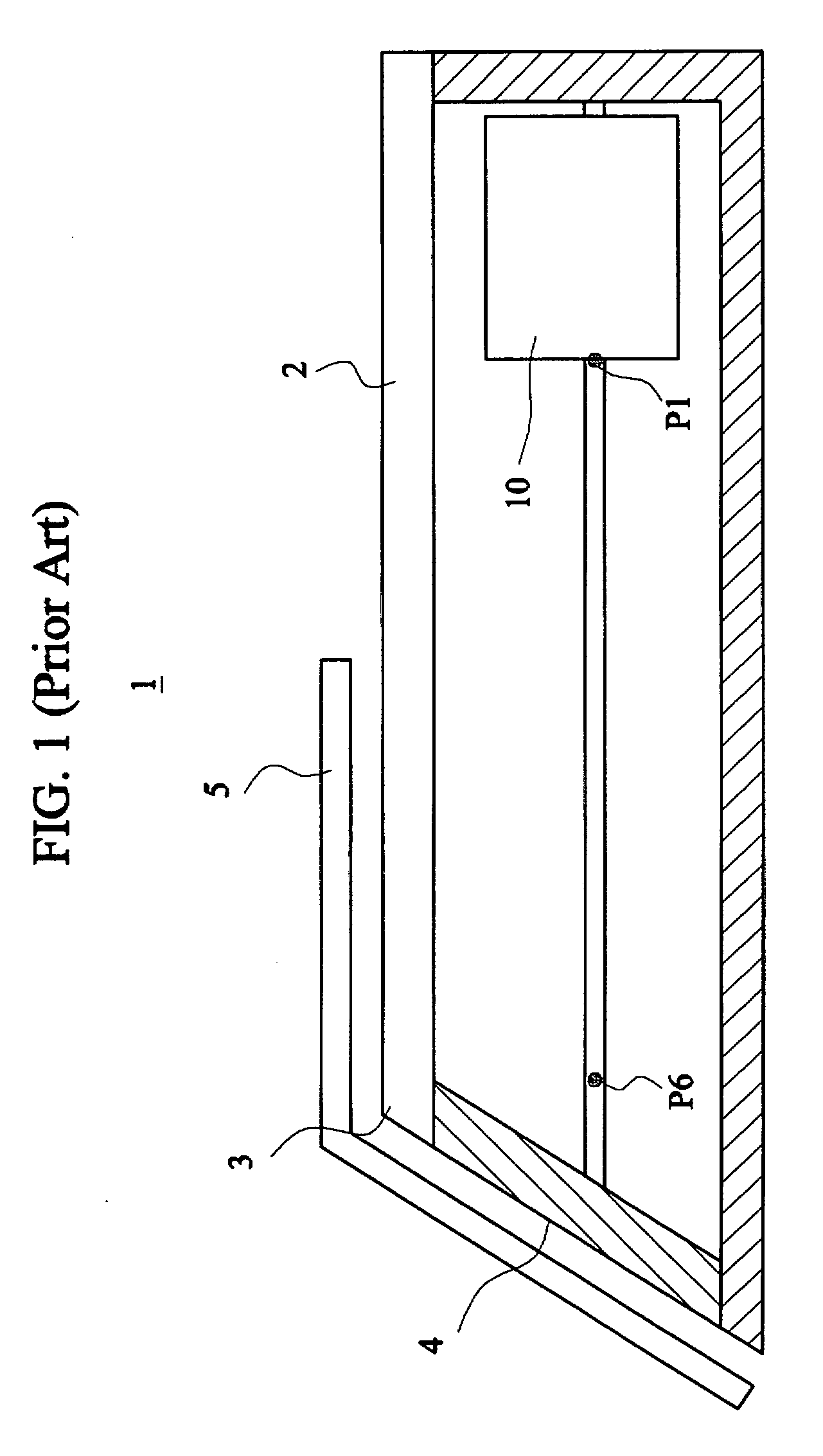
[0026]FIG. 4 shows movement stages of an optical module in a multi-stage scanning method according to the invention. As shown in FIGS. 4 and 1, the multi-stage scanning method of this embodiment is applied to a book scanner 1. The book scanner 1 has a transparent platen 2 and an inclined plane 4 connected to the transparent platen 2 to form a ridge 3. The ridge 3 supports an opened book 5 (or referred to as a document D). The ridge 3 is far away from a start position P1 of an optical module 10 and close to an end position P6 of the optical module 10. This scanning method includes the following steps.

[0027] In step S11, the optical module 10 is moved, in a forward direction, from the start position P1 to a forward-internal position P3. At this moment, the optical module 10 is accelerated to a forward speed Vf within a distance from the start position P1 to the forward-internal position P3, wherein the acceleration may be constant or variable.

[0028] In step S12, the optical module 10...

second embodiment

[0035]FIG. 5 shows movement stages of an optical module in a multi-stage scanning method according to the invention. As shown in FIGS. 5 and 1, the multi-stage scanning method of this embodiment is applied to a flatbed scanner and includes the following steps.

[0036] In step S21, an optical module 10 is moved, in a forward direction, from a start position P1 to a reverse-boundary position P2. The optical module 10 is accelerated to a first speed V1 within a distance from the start position P1 to the reverse-boundary position P2, wherein the acceleration can be constant or variable.

[0037] In step S22, the optical module 10 is enabled to scan a first portion D1 of a document D to obtain a first image until the optical module 10 reaches a reverse-internal position P4. In this embodiment, the optical module 10 scans the first portion D1 of the document D at the first speed V1.

[0038] In step S23, the optical module 10 is moved, in a reverse direction which is reverse to the forward dire...


PUM


Abstract

In a multi-stage scanning method for increasing a scanning speed and enhancing an image quality, an optical module is firstly moved from a start position to a forward-internal position in a forward direction, and then enabled to scan a first portion of a document to obtain a first image until the module reaches a forward-boundary position. Then, the module is moved from the forward-boundary position to an end position in the forward direction. Next, the module is moved from the end position to a reverse-internal position in a reverse direction, and then enabled to scan a second portion of the document to obtain a second image until the module reaches a reverse-boundary position. Then, the module is moved from the reverse-boundary position to the start position, in the reverse direction, and then stopped. Finally, the first and second images are stitched into a complete image.

Description

BACKGROUND OF THE INVENTION [0001] 1. Field of the Invention [0002] The invention relates to a multi-stage scanning method for increasing a scanning speed and enhancing an image quality, and more particularly to a multi-stage scanning method for lengthening an accelerating distance of an optical module in a scanner so as to increase the scanning speed and enhance the image quality. [0003] 2. Description of the Related Art [0004]FIG. 1 is a schematic illustration showing a conventional book scanner 1. Referring to FIG. 1, the book scanner 1 has a transparent platen 2 and an inclined plane 4 connected to the transparent platen 2 to form a ridge 3. The ridge 3 supports an opened book 5, and the ridge 3 is far away from a start position P1 of an optical module 10 and close to an end position P6 of the optical module 10. [0005]FIG. 2 shows movement stages of the optical module when the conventional book scanner of FIG. 1 is scanning a book. As shown in FIGS. 1 and 2, the conventional sca...

Claims


Application Information

Patent Timeline
IPC IPC(8): H04N1/04
CPCH04N1/1013H04N1/193H04N2201/0468H04N2201/0414H04N2201/0081
Inventor CHEN, YEN-CHENG
Owner AVISION
Why Eureka
Try Eureka