Latching solid state relay

a solid-state relay and latching technology, applied in the direction of electric switches, emergency protective circuit arrangements, electric apparatus, etc., can solve the problems of limited choice of designers who want to use an ssr in latching applications

Inactive Publication Date: 2006-11-02
CRYDOM TECH
View PDF6 Cites 11 Cited by
  • Summary
  • Abstract
  • Description
  • Claims
  • Application Information

AI Technical Summary

Problems solved by technology

Designers that want to use an SSR in latching applications are limited in their choices.

Method used


Image

  • Latching solid state relay
  • Latching solid state relay
  • Latching solid state relay

Examples


Embodiment Construction

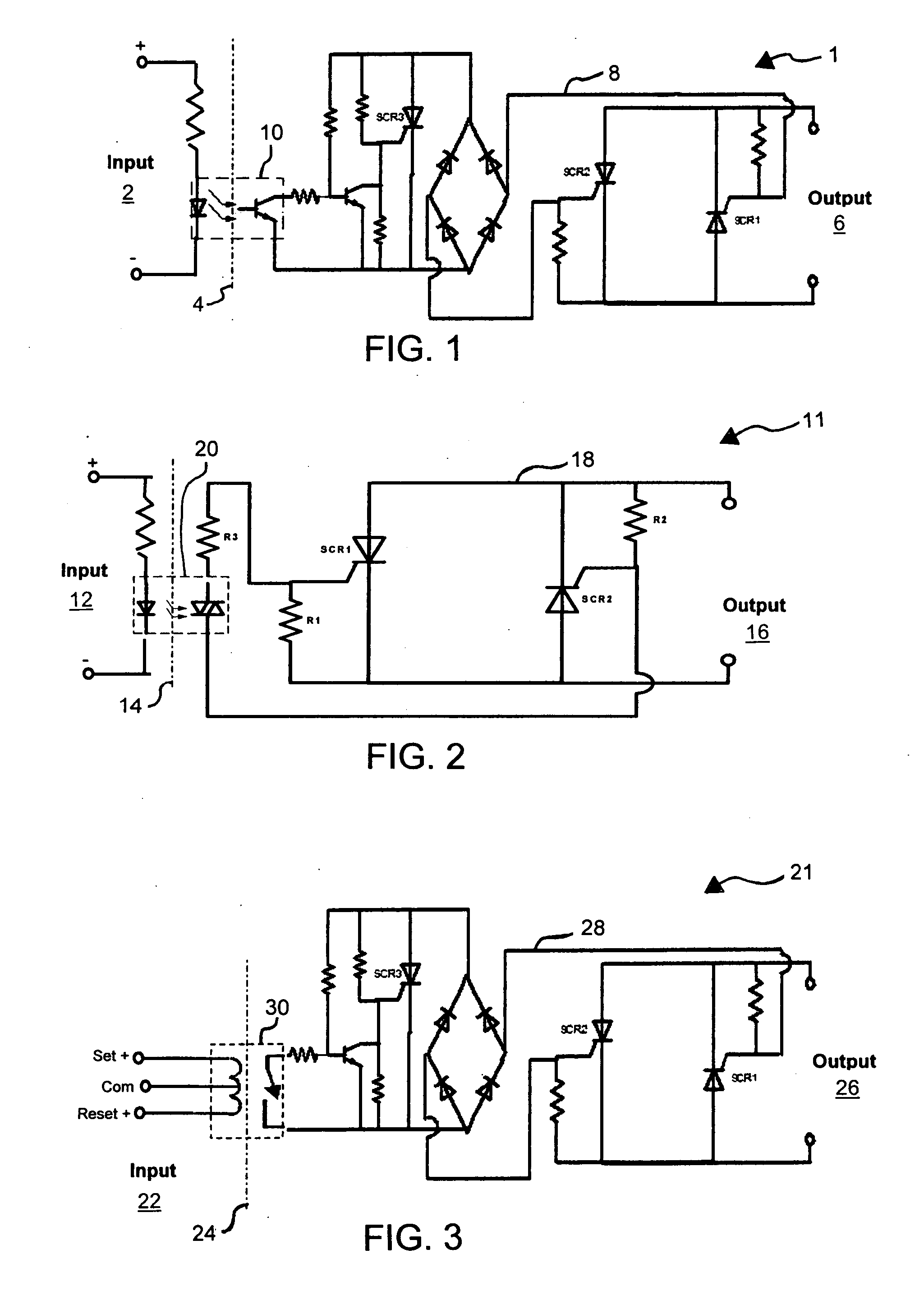
[0011] Referring now to the Figures, in which like reference numerals and names refer to structurally and / or functionally similar elements thereof, FIG. 1 shows a schematic diagram of a typical phototransistor coupled non-latching SSR circuit. Referring now to FIG. 1, Dashed Line 4 marks the isolation between the Input 2 side and the Output 6 side of Phototransistor Coupled SSR Circuit 1. Phototransistor 10 couples the signal from the Input 2 side to the SSR 8 circuit on the Output 6 side. Phototransistor 10 is non-latching. Phototransistor Coupled SSR Circuit 1 can be configured for either “zero-cross” or “random” turn-on style.

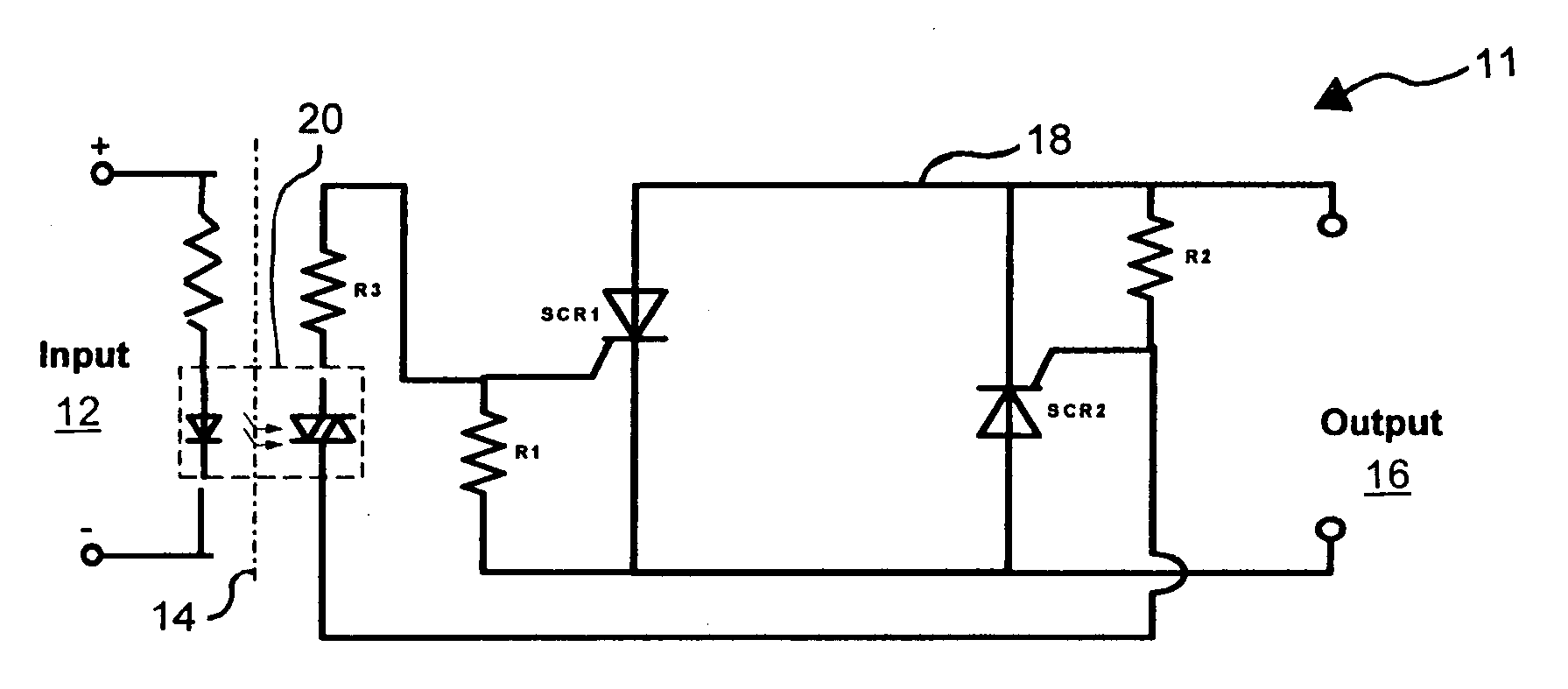
[0012]FIG. 2 shows a schematic diagram of a typical opto-triac-driver non-latching SSR circuit. Referring now to FIG. 2, Dashed Line 14 marks the isolation between the Input 12 side and the Output 16 side of Opto-Triac-Driver SSR Circuit 11. Opto-Triac-Driver 20 couples the signal from the Input 12 side to the SSR 18 circuit on the Output 16 side. Opto-Tria...


PUM


Abstract

A latching relay coupled SSR circuit provides a simple means of achieving a true latching solid-state relay in both two or three input terminal configurations, with two output terminals switched by standard solid-state relay devices. The circuit does not require any additional power sources, and has true indefinite memory retention of the last state the output was in when all power is disconnected. The latching relay coupled SSR circuit can be configured for a “zero-cross” mode of turn-on style to synchronize with the AC waveform powering the load that cannot be done with electromechanical latching relays, in addition to the purely “random” style of load switching. A latching relay is utilized. The isolation of the input side to the output side is provided by the physical separation of the coil and switch, utilizing the magnetic field of the coil to actuate the switch.

Description

FIELD OF THE INVENTION [0001] This invention relates to latching (bi-stable) relay applications, and more particularly, to a latching solid-state relay (“SSR”). BACKGROUND OF THE INVENTION [0002] Latching (bi-stable) electromechanical relays are an important segment of the overall relay market, providing contact functions that change state with a brief voltage pulse on the coil (input), and maintain that state without further energizing the input. These mechanical relays typically have either two or three terminal inputs and two output (switched) connections per pole. When using the two terminal input method, the polarity of the input signal that is momentarily applied determines the output state. When using the three terminal input method, a pulse on one terminal will “set” (close) the output of the relay, while applying a pulse to another terminal will “reset” (open) the output. The third input terminal is used as a common to both the “set” and “reset” inputs. True latching relays...

Claims


Application Information

Patent Timeline
Patent Type & Authority Applications(United States)
IPC IPC(8): H02H3/00
CPCH01H9/547H01H47/226H01H47/00
Inventor BAMBURAK, PETER KEVIN
Owner CRYDOM TECH
Why Eureka
Try Eureka