Ferroelectric memory

a technology of ferroelectric memory and peripheral circuit, applied in the field of ferroelectric memory, can solve the problems of increasing the size of the memory cell as the magnitude of multiple values, and the size of the peripheral circuit inevitably increases

Inactive Publication Date: 2005-03-22
SEIKO EPSON CORP
View PDF7 Cites 8 Cited by
  • Summary
  • Abstract
  • Description
  • Claims
  • Application Information

AI Technical Summary

Benefits of technology

According to the above-noted feature, since it is easier to produce the intermediate state of reverse polarization than to control the applied voltage, multi-value storage using the intermediate state of reverse polarization can be relatively easily attained.
According to the above-noted feature, advantageously, only one level of the applied voltage is required regardless of the magnitude of multiple values, thus making it possible to manufacture a multi-value ferroelectric memory while hardly modifying the size of a peripheral circuit.
With the above-noted feature, the two pulses ensure multi-value storage, thus achieving efficient multi-value storage. In addition, the multi-value storage is always performed in the state where the directions of polarization are the same, and the multi-value storage can therefore be stably performed.
The ferroelectric memory of the present invention provides advantages, including the fact that multi-value storage can be relatively easily performed and can be supported using the circuit of the ferroelectric memory of the related art with little modification.

Problems solved by technology

However, in the former method, since a single memory cell includes a plurality of ferroelectric capacitors, the size of the memory cell increases as the magnitude of multiple values increases.
In the latter method, since the applied voltage varies depending upon the value to be stored, the size of a peripheral circuit inevitably increases as the magnitude of multiple values increases.

Method used


Image

  • Ferroelectric memory
  • Ferroelectric memory
  • Ferroelectric memory

Examples


example 1

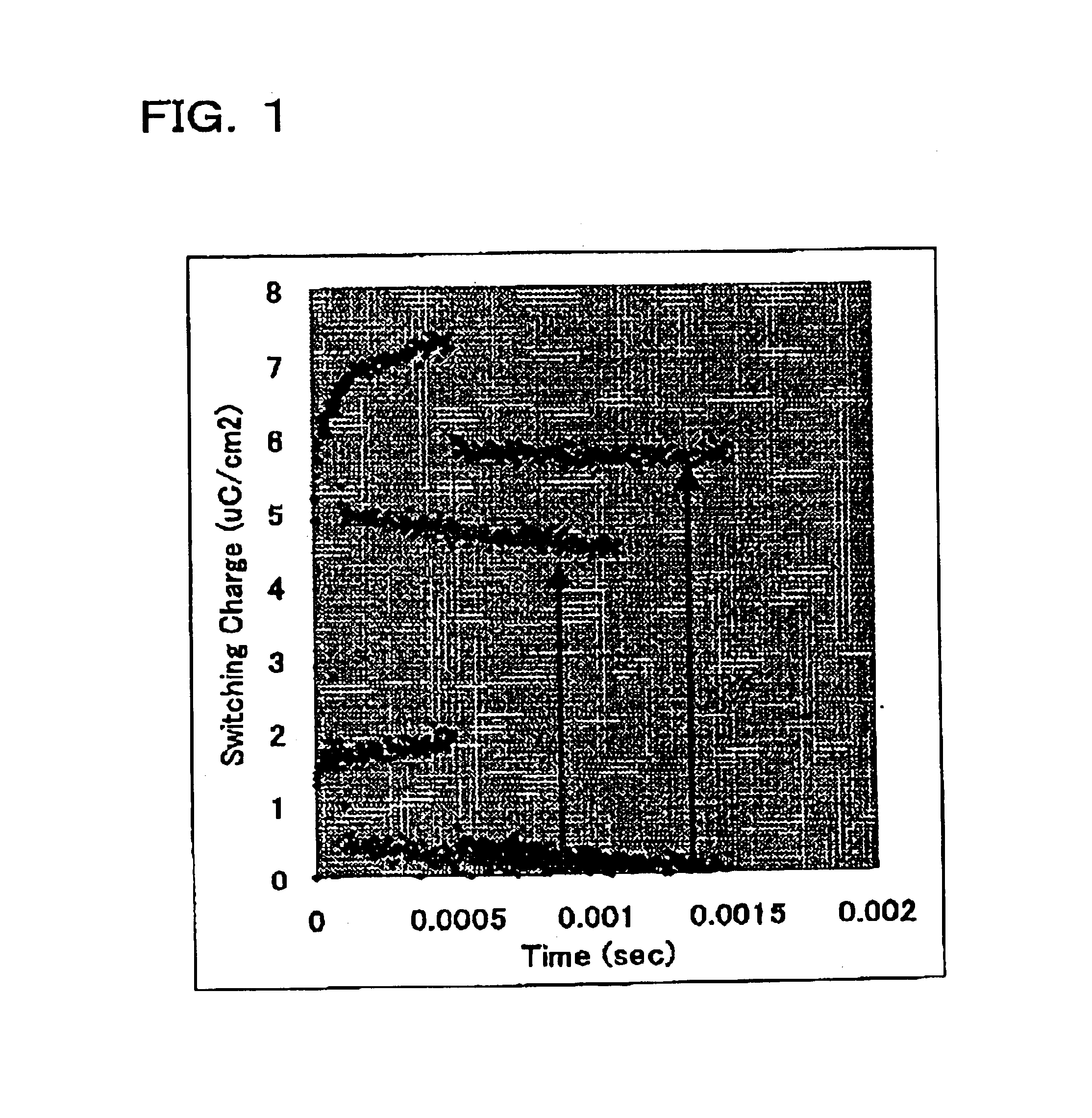
FIG. 1 is a graph showing the principle of a multi-value memory according to the present invention. In the Example, a pulse having a voltage of 1.8 V was applied to a ferroelectric capacitor having a coercive voltage of 0.9 V to perform a write operation, and the amount of reverse polarization was compared while changing the period for which the pulse is applied. As a result, it is found that the amount of reverse polarization differs depending on the difference in period for which the pulse is applied. As shown in FIG. 1, the switching charge is a function of time. Two levels of reverse polarization (“1” and “2”) correspond to two periods for which the pulse is supplied. The two levels depicted in FIG. 1 and one level without reverse polarization, i.e., a total of three levels, can be used to store three values.

example 2

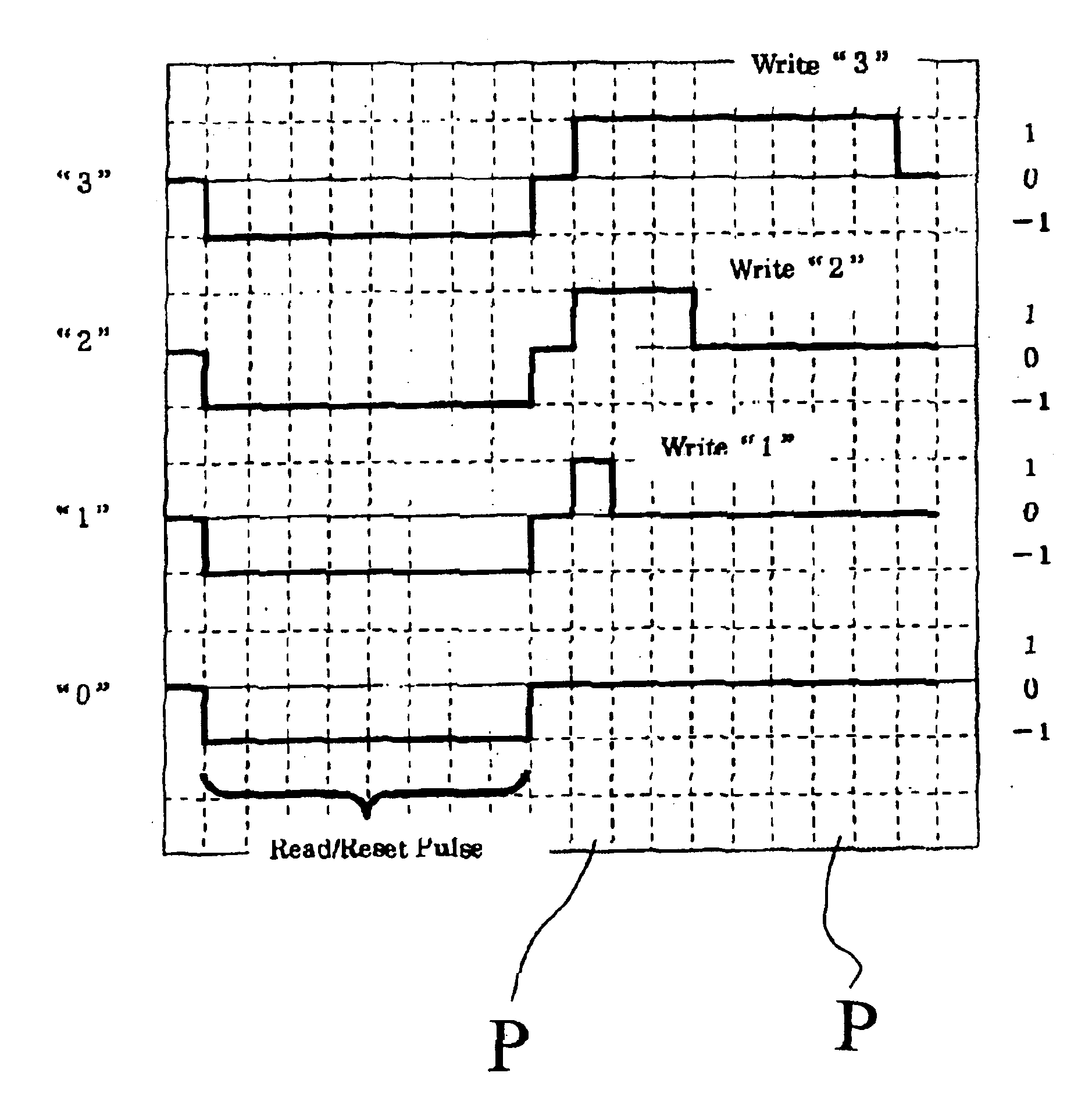
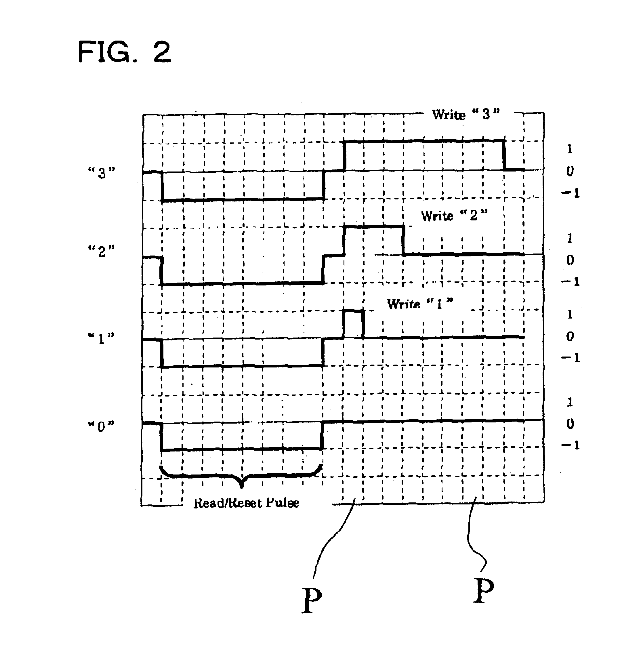
FIG. 2 is a time chart showing an exemplary write operation sequence of the ferroelectric memory according to the present invention. First, a “read / reset pulse” having a sufficient pulse width is applied so that the memory is brought into a state where polarization is saturated in one direction (“−1”). Then, a “write” pulse having a polarity reverse (“1”) to that of the above pulse and having different periods (write “1”, write “2” and “write 3”, actively) depending upon values to be stored is applied to produce the polarization states corresponding to the values, so that the information is stored. Preferably, the pulse width of the write pulse corresponding to each value is defined as an integer multiple of a certain unit time P. Preferably, the pulse width of the reset or read pulse is set to the pulse width as that of the write pulse having the longest pulse width.


PUM


Abstract

A ferroelectric memory capable of multi-value memory retention is provided which hardly modifies a related art circuit. The period for which a write pulse is applied changes depending upon a value to be stored, so that multi-value value storage is attained. Only one voltage is prepared for the write pulse, and a reset or read pulse and the write pulse have the same voltage, thus achieving a ferroelectric memory having a multi-value storage function using only one voltage source.

Description

BACKGROUND OF THE INVENTION1. Field of InventionThe present invention relates to a ferroelectric memory. More particularly, the invention relates to a ferroelectric memory to store multiple values equal to or more than three values in a single memory cell.2. Description of Related ArtA ferroelectric memory having a ferroelectric capacitor that is usable as a storage device has an operation speed as high as that of a DRAM, and is non-volatile like a FLASH memory. Due to such characteristics, the ferroelectric memory that is usable as a memory device may replace traditional memories.A related art memory device (1T1C structure, such as the example shown in FIGS. 3(a) and 3(b)), like a DRAM, is configured such that a single memory cell is formed of a transistor and a capacitor made of a ferroelectric material to ensure memory retention, and another memory device (2T2C structure) is configured such that another combination of a transistor and a capacitor for reference is added to each me...

Claims


Application Information

Patent Timeline
Patent Type & Authority Patents(United States)
IPC IPC(8): G11C11/56G11C11/22
CPCG11C11/5657G11C11/22
Inventor HAMADA, YASUAKI
Owner SEIKO EPSON CORP
Why Eureka
Try Eureka