
Terminal, system and method for providing location information service by interworking between WLAN and mobile communication network

a technology of location information and mobile communication network, applied in the field of location information system, can solve the problem that the wlan terminal cannot receive the location information service through the 3gpp network

Inactive Publication Date: 2006-11-02
LG ELECTRONICS INC
View PDF6 Cites 142 Cited by
  • Summary
  • Abstract
  • Description
  • Claims
  • Application Information

AI Technical Summary

Benefits of technology

[0044] According to another aspect, the present invention provides a method of providing a secure user plane location (SUPL) service by interworking between a mobile communication network and a wireless local area network (WLAN), wherein the mobile communication network includes an access point, a storage unit and a location server and wherein an IP connection is established between a WLAN terminal and the location server through the access point, the method comprising: requesting, by the location server, serving node routing information and capability information of the WLAN terminal from the storage unit in response to the client's location information request; and receiving, by the location server, the requested information from the database, wherein the serving node routing information received by the location server includes address information of the authentication server and terminal location related information regis

Problems solved by technology

However, because there is neither the network structure nor protocol for providing a location information service (e.g., SUPL service) in the related art system involving the conventional WLAN and 3GPP network, the WLAN terminal cannot receive the location information service through the 3GPP network according to the related art.

Method used


Image

  • Terminal, system and method for providing location information service by interworking between WLAN and mobile communication network
  • Terminal, system and method for providing location information service by interworking between WLAN and mobile communication network
  • Terminal, system and method for providing location information service by interworking between WLAN and mobile communication network

Examples


first embodiment

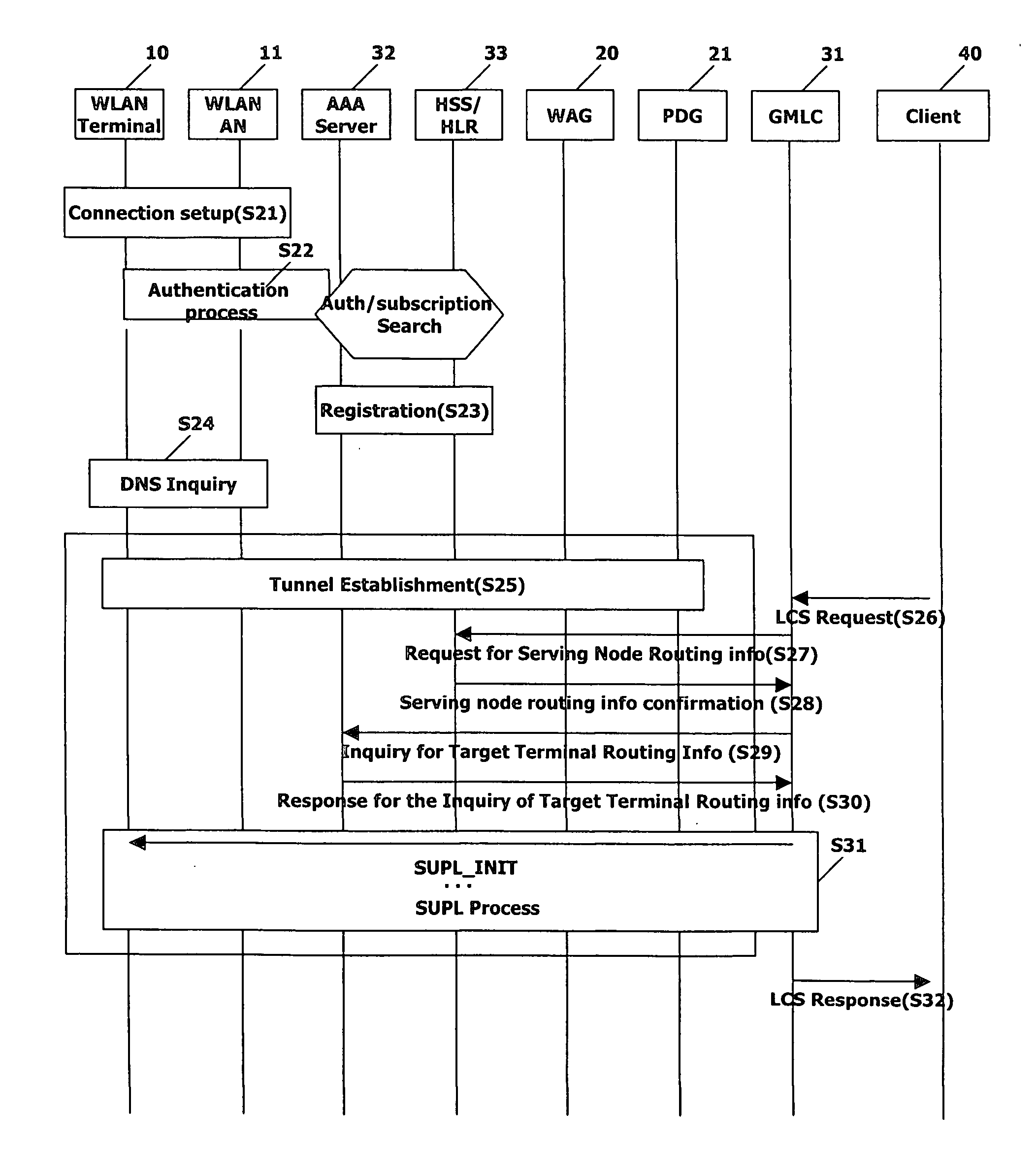
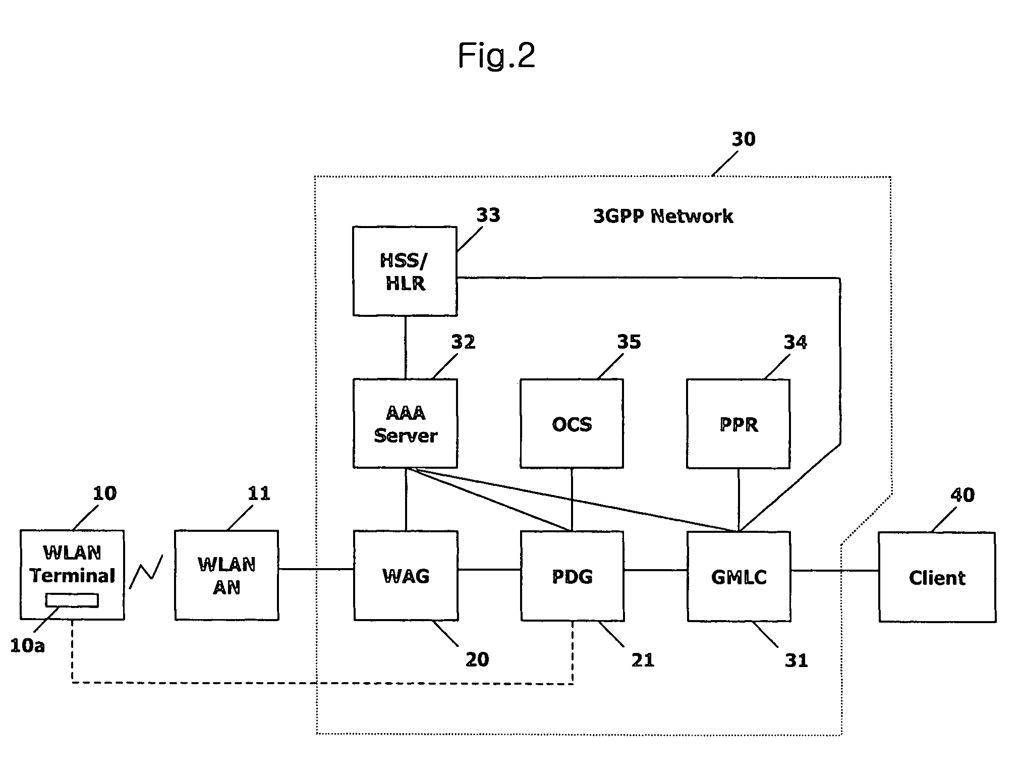
[0059]FIG. 3 is a flow chart illustrating a method for providing a location information service through interworking between the WLAN and the mobile communication network in accordance with the present invention. The method of FIG. 3 is described herein as implemented in the system of FIG. 2 as an example, but can be implemented in other suitable device / system. The processes to be performed by the WLAN terminal 10 can be performed and / or controlled by the controller 10a of the WLAN terminal 10.

[0060] Referring to FIG. 3, the WLAN terminal 10 selects a currently accessible suitable WLAN AN 11 and attempts a connection with the WLAN AN 11. When the WLAN terminal 10 is connected with the WLAN AN 11 (step S21), the WLAN AN 11 performs a mutual authentication procedure between the WLAN terminal 10 and the WLAN AN 11 through communication with the AAA server 32 of the mobile communication network 30. In this case, an EAP (Extensible Authentication Protocol) authentication procedure is per...

second embodiment

[0077]FIG. 4 is a flow chart illustrating a method for providing a location information service through interworking between the WLAN and the mobile communication network in accordance with the present invention. The method of FIG. 4 is described herein as implemented in the system of FIG. 2 as an example, but can be implemented in other suitable device / system. The processes to be performed by the WLAN terminal 10 can be performed and / or controlled by the controller 10a of the WLAN terminal 10.

[0078] Referring to FIG. 4, a process in which the WLAN terminal 10 is connected with the mobile communication network 30 through the authentication and registration procedure (steps S41˜S43) is the same as or similar to steps S21˜S23, respectively, in FIG. 3. Thus the description of steps S41 to S43 is omitted for the sake of brevity.

[0079] When a location information service request for requesting location information of a target terminal (e.g., WLAN terminal 10) is generated by the client ...

third embodiment

[0089]FIG. 5 is a flow chart illustrating a method for providing a location information service through interworking between the WLAN and the mobile communication network in accordance with the present invention. The method of FIG. 5 is described herein as implemented in the system of FIG. 2 as an example, but can be implemented in other suitable device / system. The processes to be performed by the WLAN terminal 10 can be performed and / or controlled by the controller 10a of the WLAN terminal 10.

[0090] Referring to FIG. 5, the WLAN terminal 10 selects a currently accessible suitable WLAN AN 11 and attempts a connection thereto. When the WLAN terminal 10 is connected with the WLAN AN 11 (step S61), the WLAN AN 11 performs an authentication procedure with the WLAN terminal 10 (steps S62 and S63). For instance, the WLAN AN 11 transmits an EAP (Extensible Authentication Protocol) request message to the WLAN terminal 10 (step S62), and the WLAN terminal 10 responds to the WLAN through an E...


PUM


Abstract

A WLAN terminal, system and method for providing a SUPL service, are discussed. According to an embodiment, the WLAN terminal includes a controller to establish an IP connection with a mobile communication network through interworking between the mobile communication network and a WLAN, and selectively perform a SUPL procedure with a location server of the mobile communication network through the IP connection in response to a request for location information of the WLAN terminal from the location server.

Description

[0001] This application claims the priority benefits of U.S. Provisional Application No. 60 / 690,100 filed on Jun. 13, 2005; U.S. Provisional Application No. 60 / 690,104 filed on Jun. 13, 2005; U.S. Provisional Application No. 60 / 690,107 filed on Jun. 13, 2005; U.S. Provisional Application No. 60 / 734,279 filed on Nov. 8, 2005; Korean Patent Application No. 10-2005-036513 filed on Apr. 30, 2005 in Republic of Korea; Korean Patent Application No. 10-2005-054174 filed on Jun. 22, 2005 in Republic of Korea; Korean Patent Application No. 10-2006-0012760 filed on Feb. 9, 2006 in Republic of Korea; and Korean Patent Application No. 10-2006-0029927 filed on Mar. 31, 2006 in Republic of Korea. The entire contents of each of these applications are hereby fully incorporated by reference.BACKGROUND OF THE INVENTION [0002] 1. Field of the Invention [0003] The present invention relates to a location information system and, more particularly, to a user equipment (UE), system and method for providing...

Claims


Application Information

Patent Timeline
IPC IPC(8): H04Q7/24H04W4/02H04W12/06H04W80/04H04W84/12H04W88/16H04W92/02
CPCH04L63/0272H04L63/08H04L63/0892H04L63/162H04W4/02H04W92/02H04W12/06H04W80/04H04W80/085H04W84/12H04W88/16H04W8/16
Inventor SHIM, DONG-HEE
Owner LG ELECTRONICS INC
Learn More