Modular cell site

a module cell and site technology, applied in the field of module cell sites, can solve the problem of providing uninterruptible power to the energy storage device, and achieve the effect of reducing the number of modules

Active Publication Date: 2006-11-02
T MOBILE INNOVATIONS LLC
View PDF50 Cites 24 Cited by
  • Summary
  • Abstract
  • Description
  • Claims
  • Application Information

AI Technical Summary

Problems solved by technology

In the event of a commercial AC power failure, the energy-storage device

Method used


Image

  • Modular cell site
  • Modular cell site
  • Modular cell site

Examples


Embodiment Construction

[0015] The present invention has numerous advantages over the conventional power-system housing arrangements, system installations, back-up arrangements.

[0016] For example, the disclosed embodiment takes up much less space. One module of the present invention takes up only about a 3′ by 11′ pad (33 ft2), whereas a comparable conventional BTS / VRLA arrangement would require a floor area of about 12′ by 18′ (or 216 ft2)—six times the space. If a generator is installed at the site, even more space would be required.

[0017] Also a consideration is the modular aspect of the present invention. Unlike conventional systems which are engineered for the specific requirements of a new site, or re-engineered to meet increased BTS and power requirements in expanding a site, the new modular system comes to the site ready for use. Each module comes already assembled. When additional BTS and power requirements are necessary at a new or expanding site, a module is transported to, and then incorporat...


PUM


Abstract

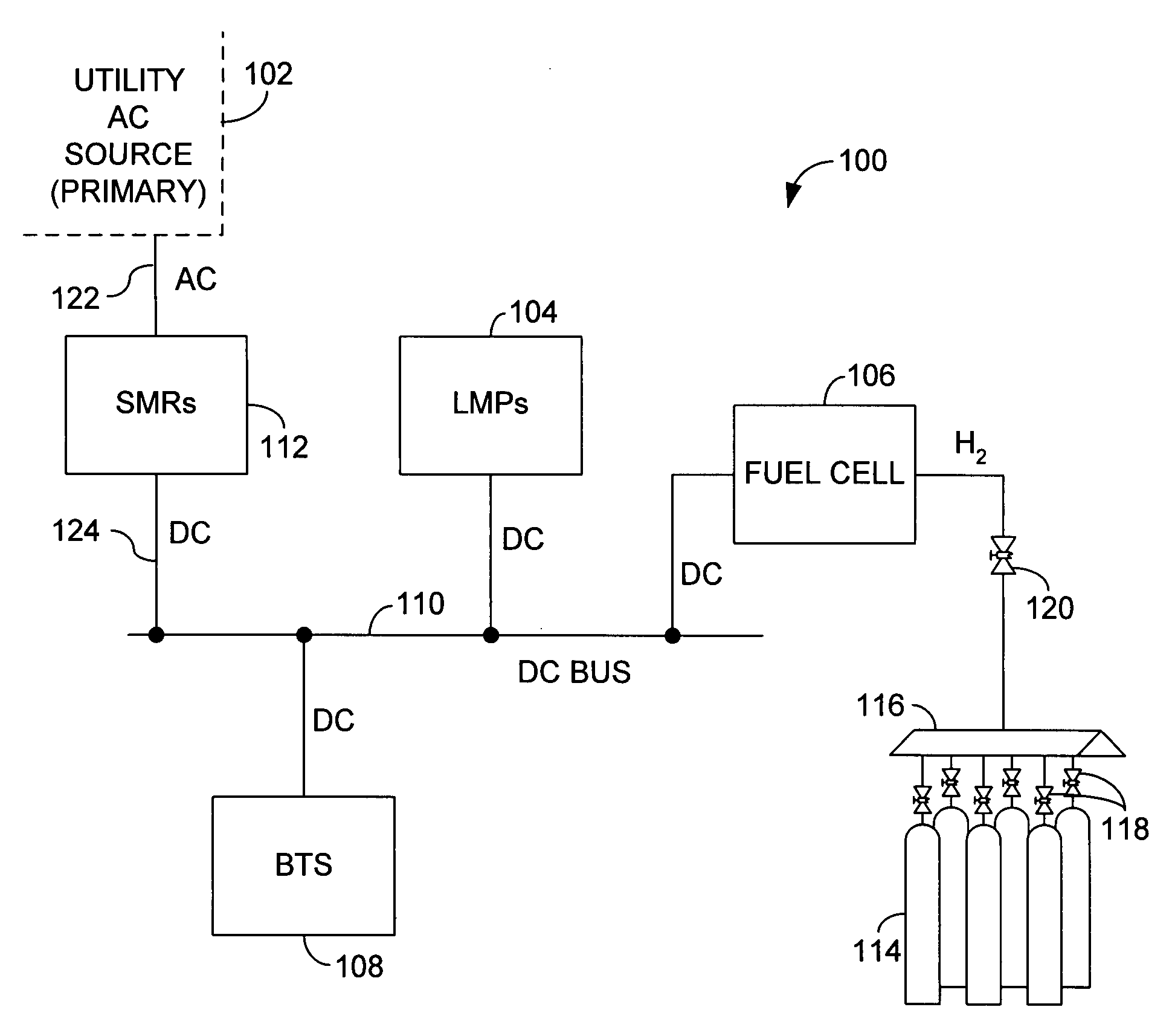
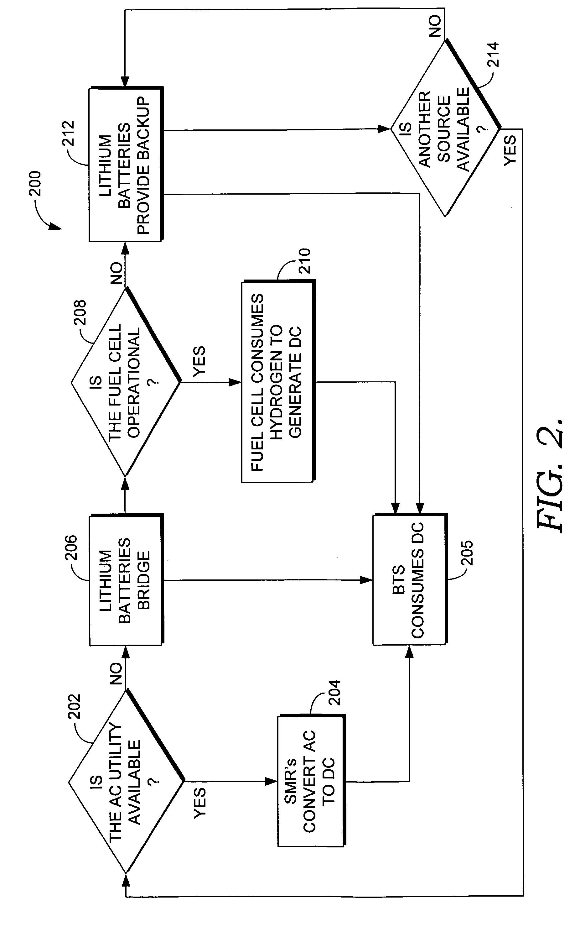
The present invention is a modular power system using a fuel cell as a back-up power supply. The system includes lithium-metal-polymer (LMP) batteries to bridge and also for backup power if necessary. The entire system is preassembled ready for use so that it is available to a new or expanding site upon delivery. The total number of modular units used can simply be aggregated to meet additional power demanded.

Description

CROSS-REFERENCE TO RELATED APPLICATIONS [0001] None. STATEMENT REGARDING FEDERALLY SPONSORED RESEARCH OR DEVELOPMENT [0002] None. FIELD OF THE INVENTION [0003] In general, this invention relates to the field of providing BTS and power equipment for use with a cell tower. More specifically, this invention relates to power-system-housing arrangements, installations, and power-backup systems. BACKGROUND OF THE INVENTION [0004] Traditionally, cell sites are constructed using commercial power from a utility as the primary source of electrical power. Telecommunications power systems include backup power arrangements to ensure continued power in the event black-outs and other disturbances in the commercial power grid. To accomplish this, many facilities use a diesel generator. The diesel generator is then backed up by an array of valve-regulated lead-acid (VRLA) batteries. The combined arrangement—the AC electrical utility receiving equipment, diesel generator, and VRLA batteries—are all s...

Claims


Application Information

Patent Timeline
IPC IPC(8): H01M8/04
CPCH01M16/006Y02E60/10Y02E60/50Y02P90/40
Inventor WILLETS, JULIE A.MEYERS, JERRY D.JOHNSON, LARRY L.
Owner T MOBILE INNOVATIONS LLC
Why Eureka
Try Eureka