Reduced NOx method of combustion

a nox method and low nitrogen oxide technology, applied in the field of low nitrogen oxide method of combustion, can solve the problems of substantial added capital expense of piping and controlling the recirculated flue gas, difficult to predict factors, and increased no/sub>x/sub>emissions, and achieve the effect of lowering nox emissions

Inactive Publication Date: 2006-11-02
HAUKE MFG
View PDF23 Cites 31 Cited by
  • Summary
  • Abstract
  • Description
  • Claims
  • Application Information

AI Technical Summary

Benefits of technology

[0009] An advantage of the present invention is that it provides a method for use with a currently installed high velocity gaseous fuel burner capable of lowering NOx emissions without altering the burner.

Problems solved by technology

A well-known problem in the industry for many years with the use of conventional burner designs utilizing preheated combustion air is higher flame temperatures which in turn contribute to an exponential increase in NOx emissions.
However, these factors are difficult to predict because burners for different industrial processes must operate at various furnace chamber temperatures, have various oxygen concentrations in the work chambers, may or may not have preheated combustion air, and are required to operate at different heat inputs depending on changing heat load requirements.
However, the added capital expense for piping and controlling the recirculated flue gases are substantial.

Method used


Image

  • Reduced NOx method of combustion
  • Reduced NOx method of combustion
  • Reduced NOx method of combustion

Examples


Embodiment Construction

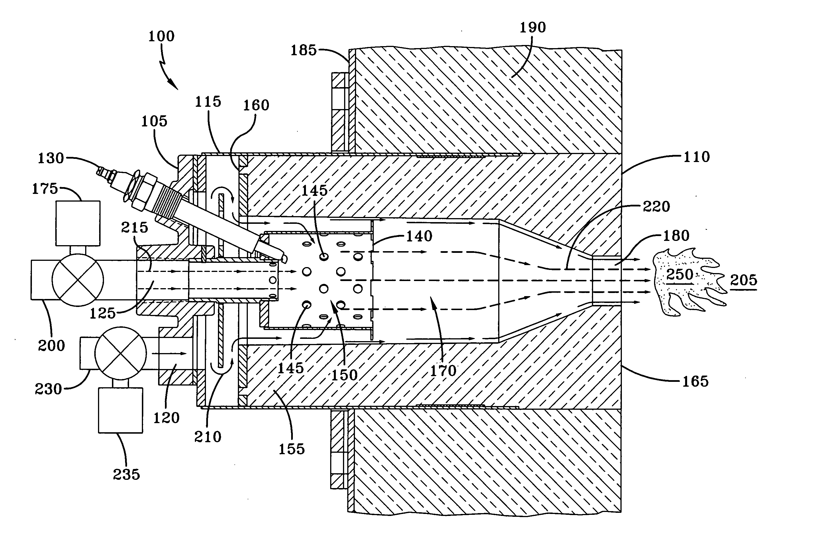
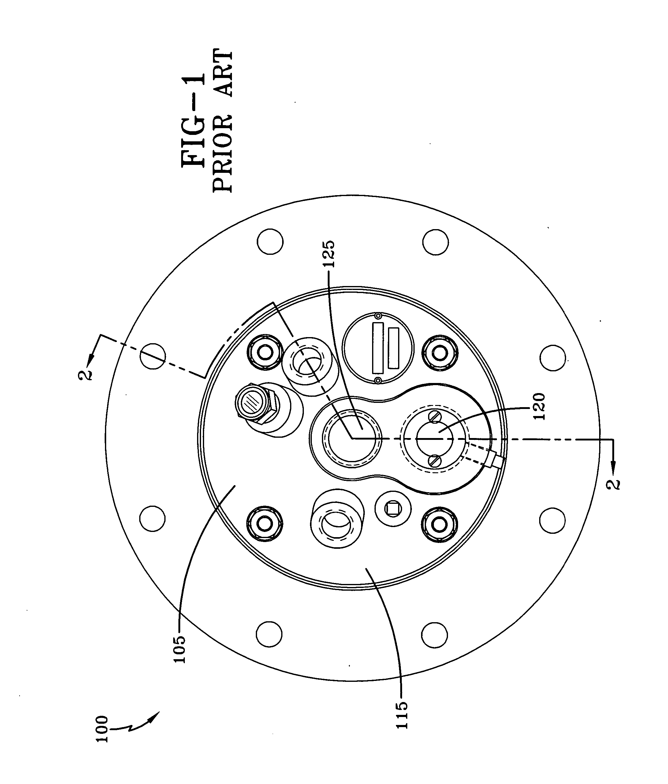
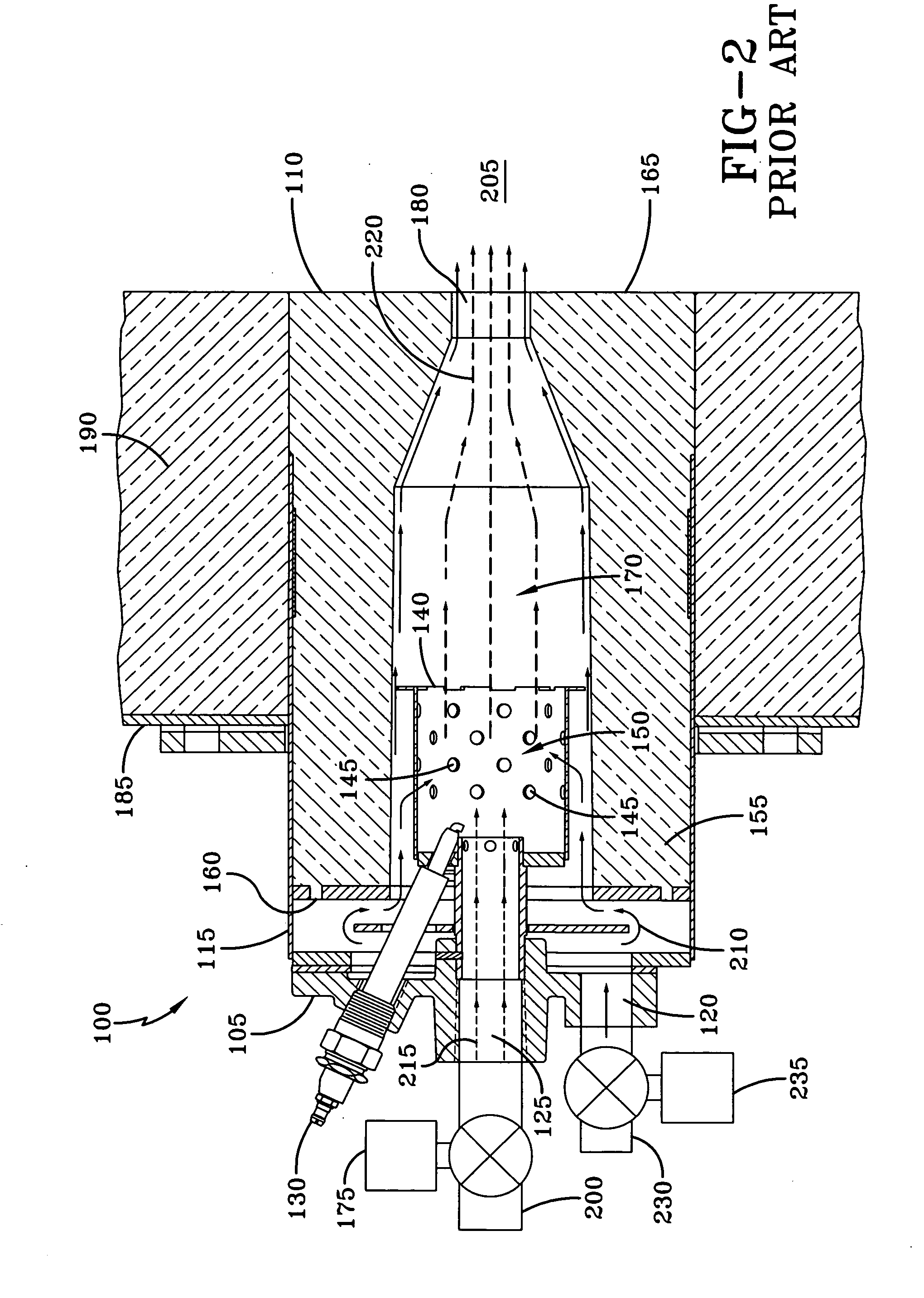
[0020]FIG. 1 depicts an end view of an exemplary prior art high velocity burner 100 designed for firing on gaseous fuel, while FIG. 2 depicts a cross-sectional view of the prior art burner of FIG. 1 taken along line 2-2. The high-velocity burner 100 has an upstream end 105 and a downstream end 110. Additionally, the burner 100 has a main burner body 115, with a combustion air inlet passage 120 and a gaseous fuel inlet passage 125 located within the main burner body 115. A flame igniter 130 and flame detector (not shown) are disposed in the main burner body 115. The main burner body 115 also has a flame stabilizer 140 disposed within the body 115, the flame stabilizer 140 having a structural element that functions as a means of mixing fuel and air, such as, for example, apertures 145, and a flame stabilizer chamber 150 disposed within the flame stabilizer 140. Attached to the main burner body 115 is burner tile 155, having an upstream end 160 and a downstream end 165. The burner tile...


PUM


Abstract

The present invention is a method for achieving low NOx single-stage combustion. A high velocity burner is run normally, with combustion occurring within both the burner combustion chamber and furnace chamber, until the gases within the furnace exceed the auto-ignition temperature of the gaseous fuel. The gaseous fuel is then shut off until the temperature within the burner combustion chamber drops below the auto-ignition temperature of the gaseous fuel. The gaseous fuel is then turned back on and the gaseous fuel auto ignites within the furnace chamber. The combustion then occurs only within the furnace chamber and not in the burner combustion chamber.

Description

CROSS-REFERENCE TO RELATED APPLICATIONS [0001] This application claims the benefit of U.S. Provisional Application No. 60 / 675,975 filed Apr. 29, 2005, which application is hereby incorporated by reference in its entirety.FIELD OF THE INVENTION [0002] The present invention is generally directed to a method of combustion and specifically directed to a low nitrogen oxide method of combustion. BACKGROUND OF THE INVENTION [0003] One of the by-products created by the combustion of hydrocarbon (HC) fuels in burners that use atmospheric air is nitrogen oxide (NOx). A well-known problem in the industry for many years with the use of conventional burner designs utilizing preheated combustion air is higher flame temperatures which in turn contribute to an exponential increase in NOx emissions. Efforts to save fuel and increase combustion efficiency via recuperative and / or regenerative combustion systems combined with increasingly strict governmental regulations to achieve acceptable NOx emissi...

Claims


Application Information

Patent Timeline
Patent Type & Authority Applications(United States)
IPC IPC(8): F23D11/44
CPCF23C3/002F23C99/00F23C2900/99001F23D14/84F23C2900/03005F23D14/82Y02E20/342Y02E20/34
Inventor FEESE, JAMES J.GATTO, BENJAMINLISIN, FELIX
Owner HAUKE MFG
Why Eureka
Try Eureka