Pneumatic devices for personal protection and relevant article of clothing including such device

a technology of personal protection and pneumatic device, which is applied in the direction of chemical protection, nuclear engineering, nuclear elements, etc., can solve the problems of general decreasing in the effectiveness of the protection device, subject to a change in the geometric shape, and the region of the body which is protected, so as to limit the change in the width

Inactive Publication Date: 2006-11-09
ANTONIO PRIMO COLOMBO +1
View PDF5 Cites 22 Cited by
  • Summary
  • Abstract
  • Description
  • Claims
  • Application Information

AI Technical Summary

Benefits of technology

[0013] The object of the present invention is, therefore, to improve the effectiveness of protecting devices known in the art of the kind described above by using a device aimed at limiting the drawbacks connected with the unavoidable change in the geometric shape of the gas-tight chamber upon its inflation.
[0016] The solution to this technical problem is given in that the flexible partition members arranged inside the gas-tight chamber contribute to greatly limit the changes in the width of gas-tight chamber in passing from a deflated condition to an inflated condition and cause the thickness of the gas-tight chamber in the inflated condition to be the most uniform as possible, so that the protecting features are substantially the same in all points of the region of the body of a motorcycle rider for which protection is sought.

Problems solved by technology

A drawback which is to be found in a protecting device of the kind described above is depending on the fact that the gas-tight chamber, when inflated, is subject to a change in its geometric shape under the action of the pressure exerted by the gas introduced thereinto.
As a result of the inflation of the tubular element, it follows that there is a diminishing of the region of the body which is protected and, therefore, a general decreasing in the effectiveness of the protecting device.
This fact also is detrimental to the effectiveness of the protecting device.

Method used


Image

  • Pneumatic devices for personal protection and relevant article of clothing including such device
  • Pneumatic devices for personal protection and relevant article of clothing including such device
  • Pneumatic devices for personal protection and relevant article of clothing including such device

Examples


Embodiment Construction

[0026] In the following description, Part 1 describes a pneumatic device for personal protection. Part 2 describes an article of clothing including the device. Part 3 describes the mode of use of the article of clothing and the operation of the pneumatic device for personal protection. Part 4 highlights the main features of the pneumatic device for personal protection and the relevant article of clothing containing such a device, in connection with the achievement of the object aimed at of the present invention. At last, Part 5 provides results of tests carried out on a model of the present invention.

1. The Pneumatic Device for Personal Protection.

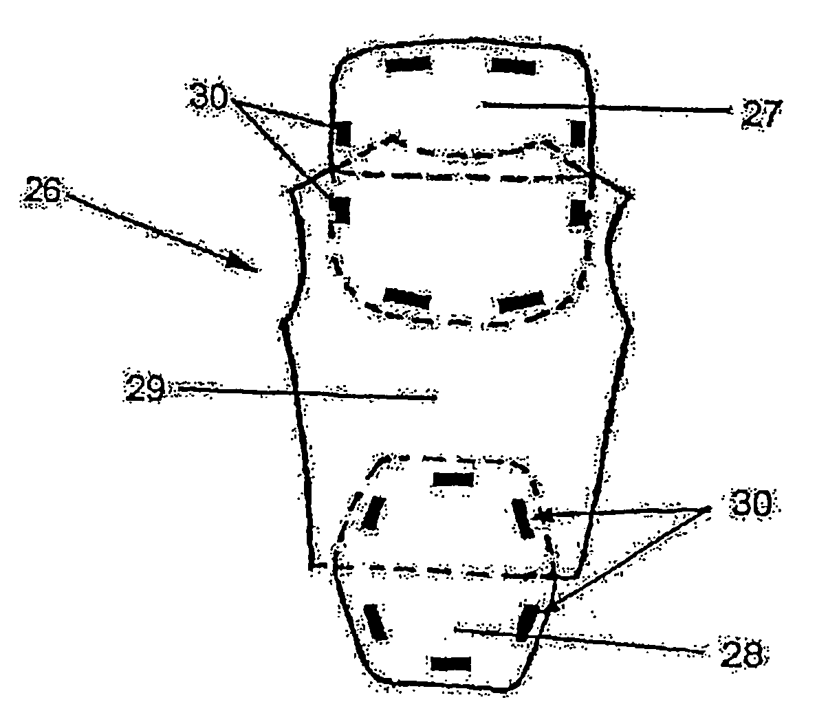
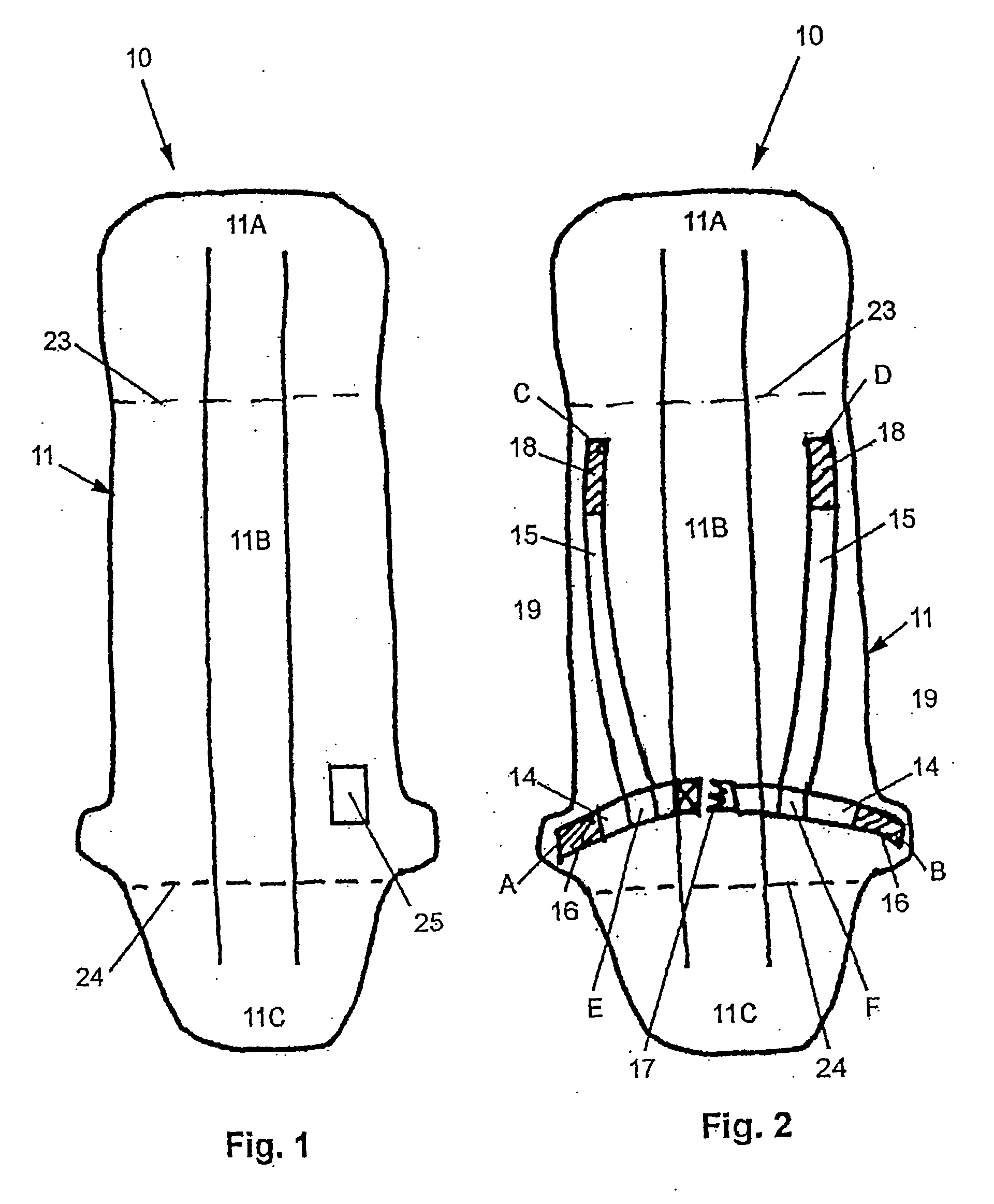
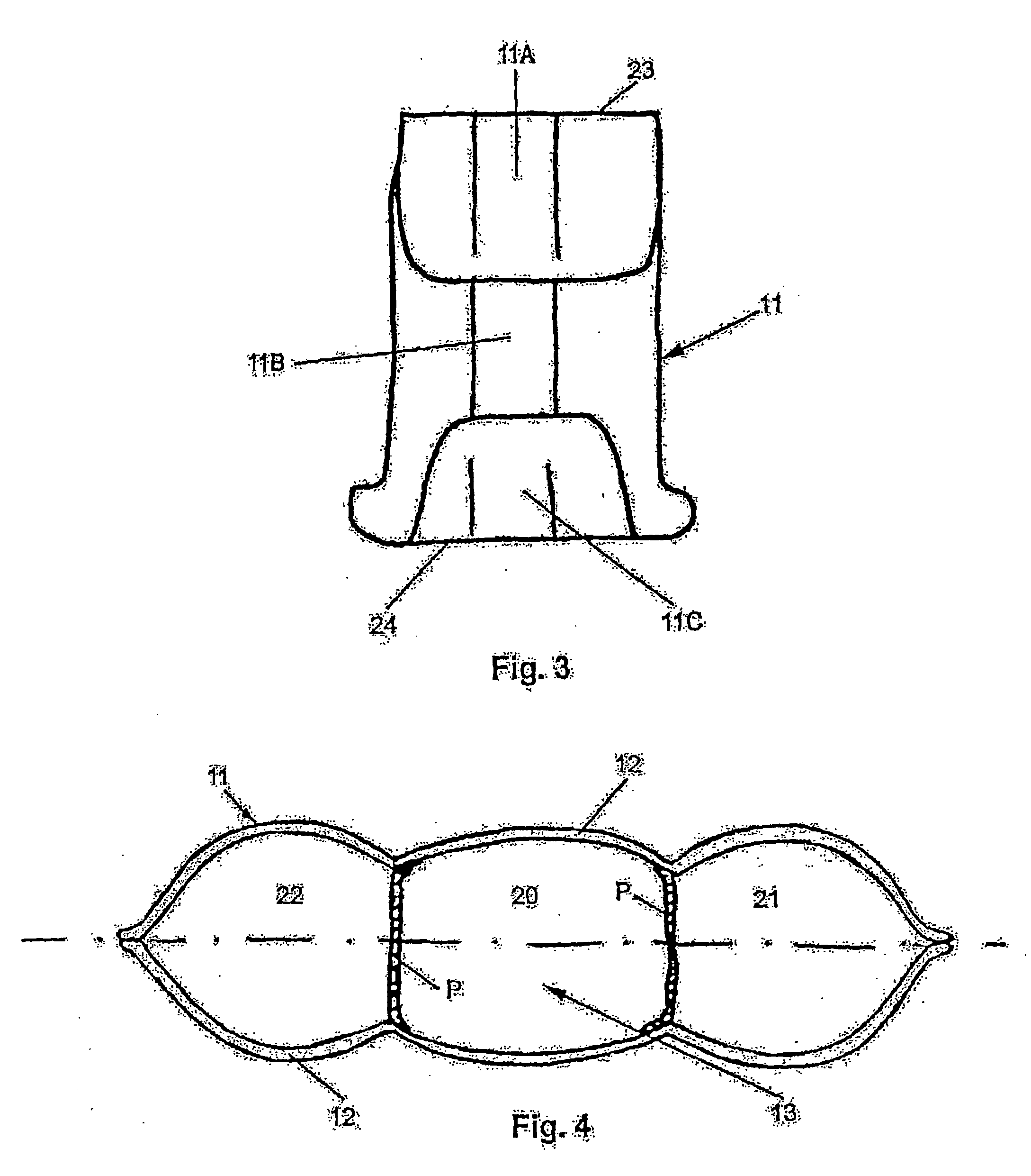
[0027] FIGS. 1 to 4 illustrate the pneumatic device for personal protection according to the present invention, generally designated by 10. The device consists of a sac-like gas-tight element 11 formed of a pair of impervious or adequately gas-tight (controlled permeability) sheets 12 sealed to each other at their respective edges. The ...


PUM


Abstract

The pneumatic device for personal protection (10) is of the king having at least one sac-like gas-tight element (11) connectable through an inlet boy (25) to automatically releasing inflating means and attaching means (14, 15) co-operating, in working position, with the body of a user so that the saclike element (11) is kept in a position which corresponds to the portion of the body to be protected. The sac-like element (11) encloses a variable volume chamber (13) which is intended to be filled with a gas introduced therein via said inlet box (25). The chamber (13) comprises inside flexible partition members (P) extending lengthwise a greater side of the chamber (13) and connected along their edges extending lengthwise to two opposite walls (12) of the chamber (13). The flexible partition members (P) divide the chamber (13) into a plurality of compartments (20, 21, 22) arranged one next to another and in fluid communication with each other.

Description

TECHNICAL FIELD [0001] The present invention relates to a pneumatic device for personal protection, particularly for motorcycle riders, horse riders and the like, and to an article of clothing including such a device. [0002] The present invention is included in the technical field of personal protecting devices and garments for protecting human beings in the case of an accidental fall off from a two-wheeled vehicle and, more generally, from any motor-driven and motorless vehicle, horses and the like or equipment for leisure / work activities, wherein the body of a human being is exposed to the risk of severe injuries upon an impact against the ground or an obstacle. [0003] Devices of this kind are already known in the art and are made according to various embodiments. BACKGROUND ART [0004] Document EP 0 043 990 B1 offers an example of an embodiment similar to that of the present invention, although in a limited extent with regard to some common features. [0005] In the document mention...

Claims


Application Information

Patent Timeline
Patent Type & Authority Applications(United States)
IPC IPC(8): A41D13/015A41D13/018A62B99/00
CPCA41D13/018
Inventor COLOMBO
Owner ANTONIO PRIMO COLOMBO
Why Eureka
Try Eureka