Connection device, image forming apparatus and optional device equipped with the same

a technology of image forming apparatus and connection device, which is applied in the direction of coupling device connection, metal sawing accessories, instruments, etc., can solve the problems of reducing the effort required for detaching the sheet processor from the rail, and achieves the effects of convenient attachment and detachment, easy electrical conduction, and safe for the user

Active Publication Date: 2006-11-09
KYOCERA DOCUMENT SOLUTIONS INC
View PDF6 Cites 12 Cited by
  • Summary
  • Abstract
  • Description
  • Claims
  • Application Information

AI Technical Summary

Benefits of technology

[0021] According to this structure, it is easy to attach and detach the device having the connection device of the present invention to and from another device, and an electrical conduction between the devices can be formed easily. In addition, the devices can be fixed to each other when the device having the connection device of the present invention is attached to the other device. In addition, since the conductive member is not exposed to the outside of the device, it is safe for the user.
[0022] An image forming apparatus according to the present invention includes the connection device described above. According to this structure, it is easy to attach and detach the optional device to and from the image forming apparatus. In addition, it is easy to form an electrical conduction between the image forming apparatus and the optional device.
[0023] The optional device according to the present invention has a structure with the connection device described above. According to this structure, it is easy to attach and detach the optional device to and from a device to which the optional device is connected. In addition, it is easy to form an electrical conduction between the optional device and a device to which the optional device is connected.
[0024] As described above, according to the connection device of the present invention and the image forming apparatus having the connection device as well as the optional device having the connection device, it is easy to attach and detach one of the devices with the connection device to and from the other device. In addition, it is easy to form an electrical conduction between the devices.

Problems solved by technology

However, the conventional connection device 71 has a problem as follows.
In addition, the image forming apparatus including the connection device disclosed in JP-A-11-193136 has a disadvantage of much effort necessary for detaching the sheet processor from the rail when a malfunction occurs in the sheet processor since the sheet processor (corresponding to the sheet loading device) is connected to the conductive rail that is connected to the paper feed device.

Method used


Image

  • Connection device, image forming apparatus and optional device equipped with the same
  • Connection device, image forming apparatus and optional device equipped with the same
  • Connection device, image forming apparatus and optional device equipped with the same

Examples


Embodiment Construction

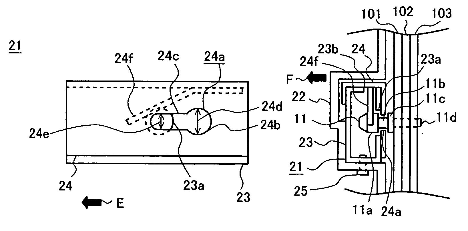
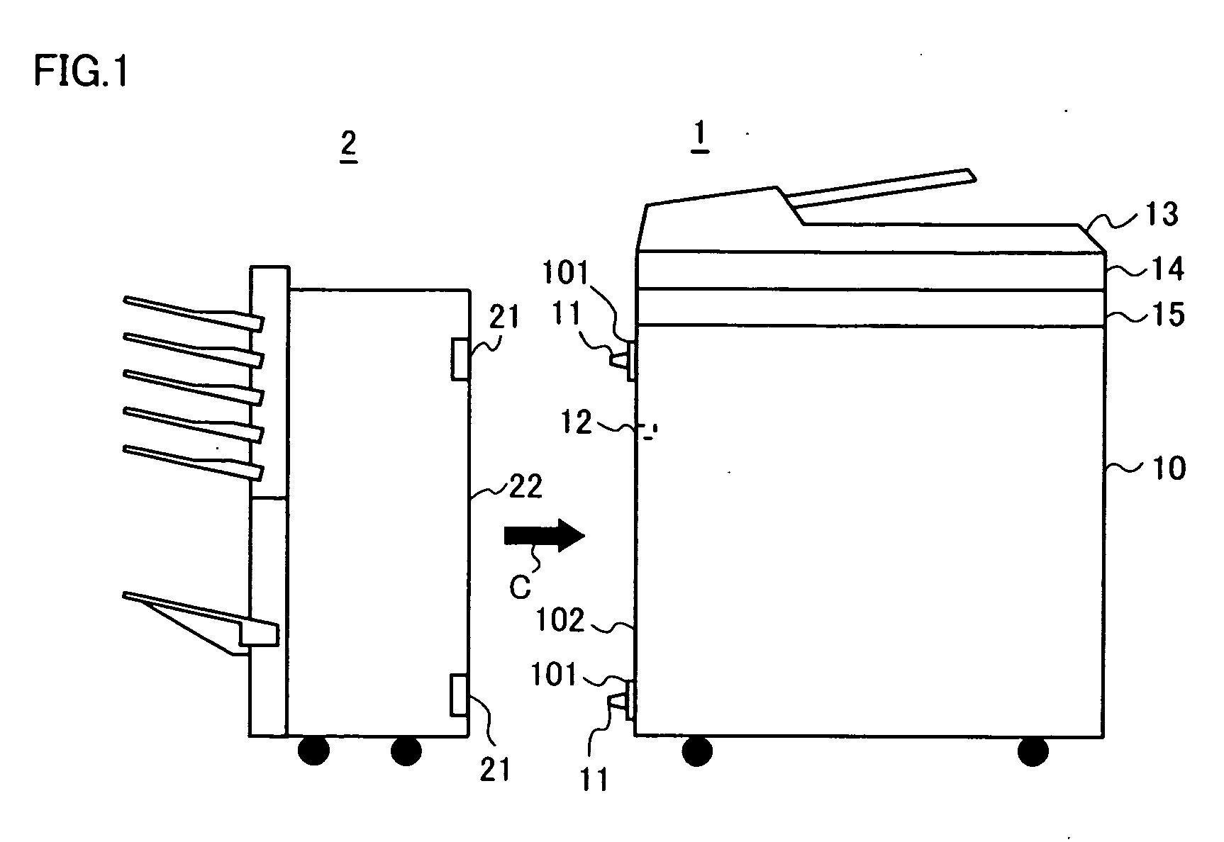
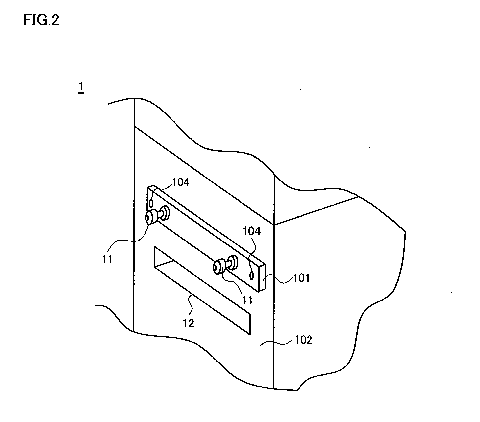
[0037] Hereinafter, an example of the present invention will be described. In the example, a connection device according to the present invention is applied to a post processor (corresponding to a first device) that is an optional device of a copying machine (corresponding to a second device). FIG. 1 is an elevation view showing schematically a post processor and a copying machine that are equipped with a connection device according to the present invention. FIG. 2 is a perspective view showing schematically positioning pins arranged at a vicinity of a paper delivery portion 12 of the copying machine 1. FIGS. 3A-3C are diagrams for explaining a structure of the main portion of the connection device that is provided to the post processor and its connection with the copying machine. FIG. 3A shows the connection device before the post processor is attached to the copying machine. FIG. 3B shows connection between the copying machine and the post processor when a movable locking member o...


PUM

PropertyMeasurementUnit
conductiveaaaaaaaaaa
diameteraaaaaaaaaa
electrical conductionaaaaaaaaaa

Abstract

A connection device includes a fixed locking member that is connected electrically to a conductive first frame of a post processor, and a conductive movable locking member that contacts an outer face of the fixed locking member and can slide. A conductive positioning pin that is connected electrically to a conductive second frame of a copying machine is inserted in a pin insertion hole and a large diameter portion in an unlock position of the movable locking member. When the movable locking member is further moved to slide to a lock position, the positioning pin is engaged and fixed to a small diameter portion, so that a conductive plate spring of the movable locking member contacts the positioning pin.

Description

[0001] This application is based on Japanese Patent Application No. 2005-136024 filed on May 9, 2005, the contents of which are hereby incorporated by reference. BACKGROUND OF THE INVENTION [0002] 1. Field of the Invention [0003] The present invention relates to a connection device for connecting an optional device to a main body and making an electrical conduction between them. The present invention also relates to an image forming apparatus and an optional device equipped with the connection device. [0004] 2. Description of Related Art [0005] Conventionally, a mechanical connection as well as an electrical conduction is realized between an image forming apparatus and an optional device, i.e., a post processor (that performs post processes such as a sorting process, a stapling process and a punching process of delivered paper sheets) in the following way using a conventional connection device. Note that the electrical conduction is necessary for preventing a malfunction or the like...

Claims


Application Information

Patent Timeline
Patent Type & Authority Applications(United States)
IPC IPC(8): B27B9/02
CPCG03G21/1652G03G2221/1654G03G2221/166
Inventor MASAI, KATUNORI
Owner KYOCERA DOCUMENT SOLUTIONS INC
Why Eureka
Try Eureka