Improved Universal Machinery Fence System

a technology of fence system and machinery, which is applied in the direction of metal-working machine components, flat surface machines, manufacturing tools, etc., can solve the problems of not being able to adjust the fence extrusion square to the table, compromising the fit between the t-slot and the mating fence mechanism, and not being able to accommodate the fence system availabl

Inactive Publication Date: 2006-11-09
KREG ENTERPRISES
View PDF45 Cites 45 Cited by
  • Summary
  • Abstract
  • Description
  • Claims
  • Application Information

AI Technical Summary

Benefits of technology

[0018] In an especially preferred form, the track of the rail and the clamp block have mating angled surfaces, preferably of a standard dovetail angle, with the angled surface on the rail being angled so as to face downwardly and the mating surface on the clamp block being angled at a mating angle and so as to face upwardly. A screw knob opposite from the angled face of the clamp block that is screwed into the clamp block bears against the side of the track that is opposite from the angled face of the track so that when the screw knob is tightened, the two angled faces are forced into abutment with one another, which tends to hold the clamp block down against the track. The screw knob can be loosened to slide the clamp block along the track

Problems solved by technology

The mechanism for securing the fence to the machine has been with the use of the extrusion T-slots which are cumbersome and requires sliding the fence mechanism to the end of the track to release the fence from the T-slot.
There is always a slight variation in the extrusion which compromises the fit between the T-slot and the mating fence mechanism.
When using the T-slot mechanism to mount a rip fence, adjusting the fence extrusion square to the table, which is desirable for the band saw, is problematic.
No mechanism allows a fence to easily be moved from one side of a band saw blade to the opposite side of the blade or allows the same fence to be moved quickly from one machine to another such as from the drill press, router tab

Method used


Image

  • Improved Universal Machinery Fence System
  • Improved Universal Machinery Fence System
  • Improved Universal Machinery Fence System

Examples


Embodiment Construction

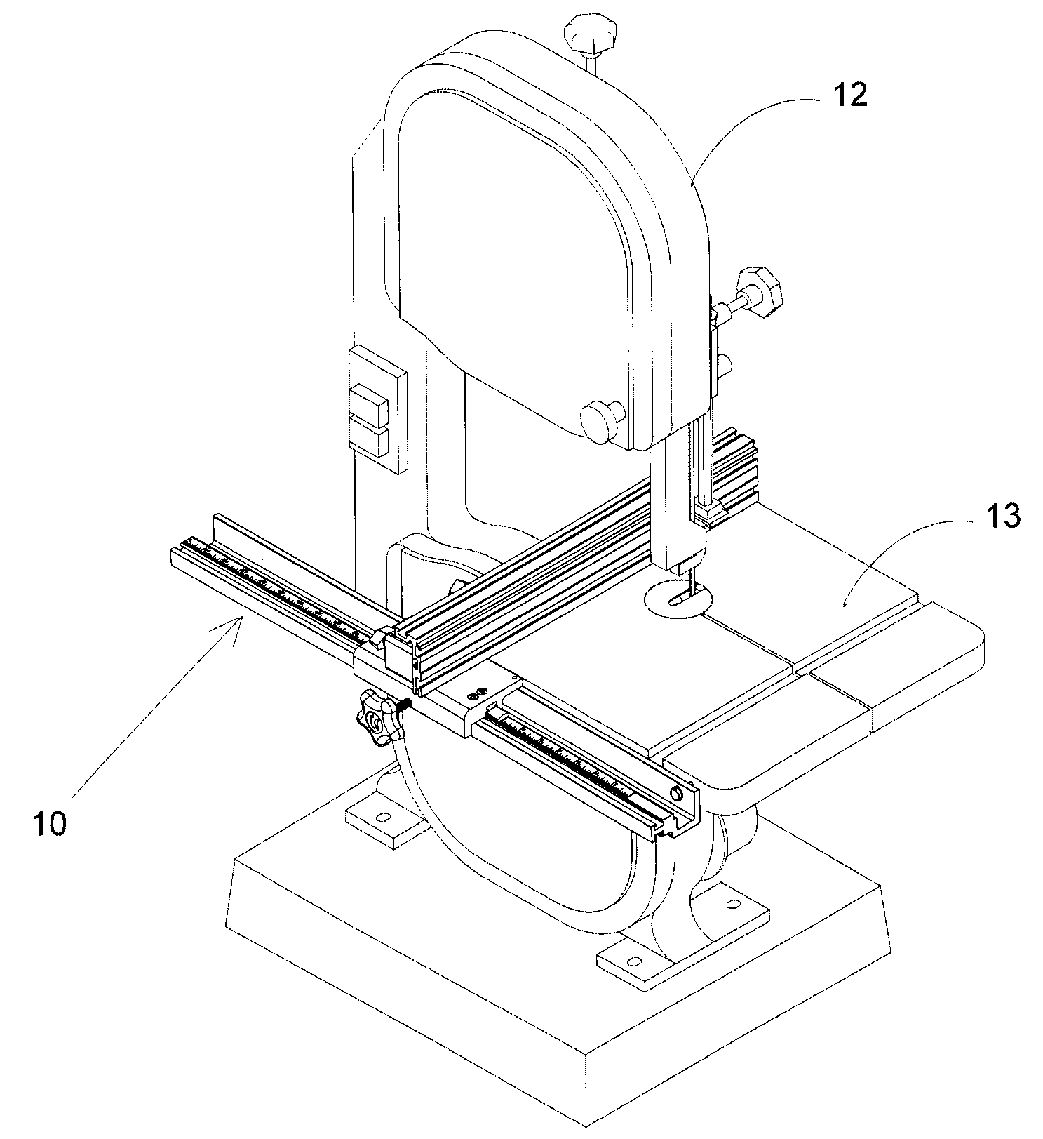
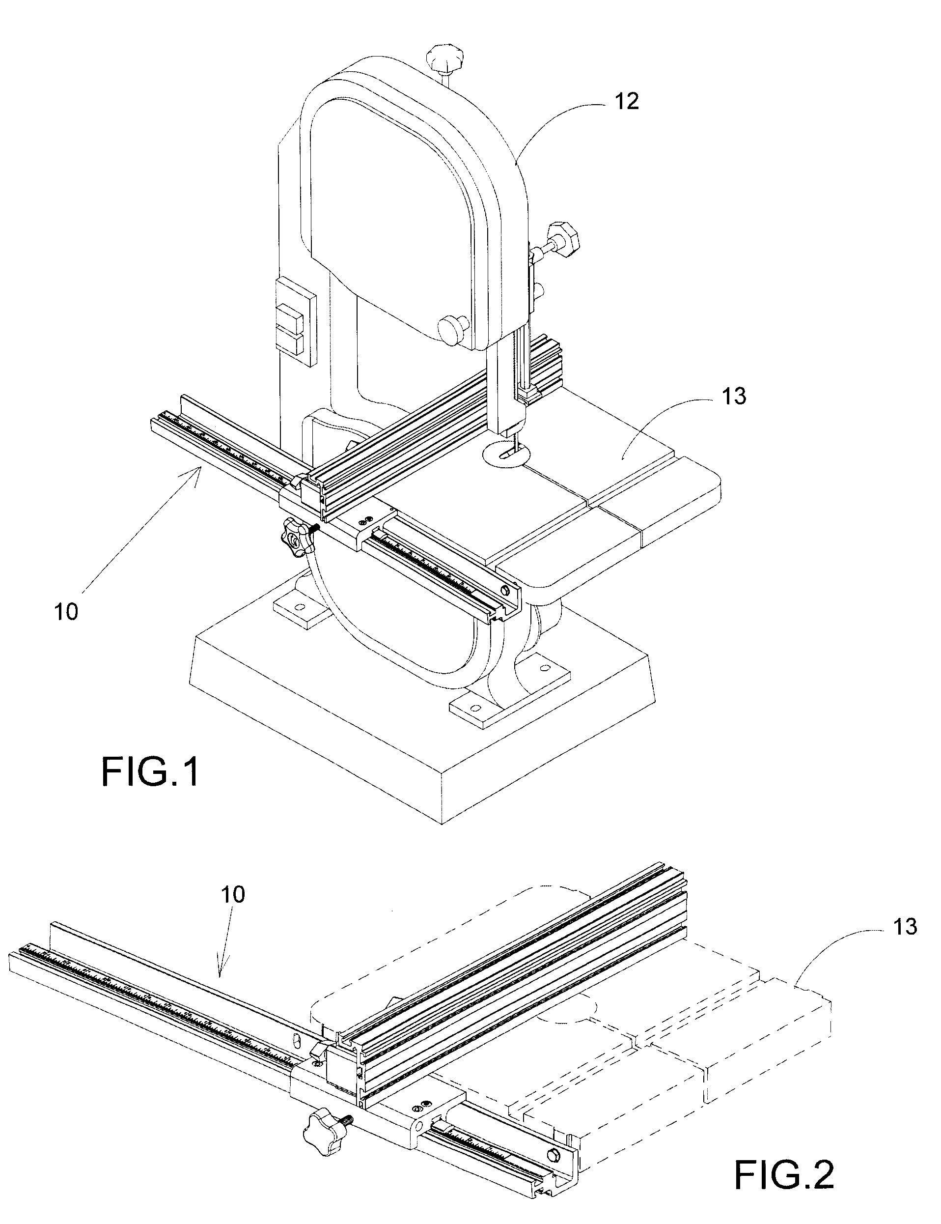
[0132]FIG. 1 illustrates a rip fence system 10 of the invention positioned on the U-shaped dovetail track rail 20 as it is used on a band saw 12. The L-shaped extrusion of U.S. patent application Ser. No. 10 / 944,035, is used as a band saw fence rather than a crosscut fence. The rip fence system 10 of the invention is secured to the front of the band saw table 13.

[0133]FIG. 2 is an enlarged perspective view of the rip fence system 10 of the invention positioned on the U-shaped dovetail track rail 20 as it is used on a cast iron machine table 13.

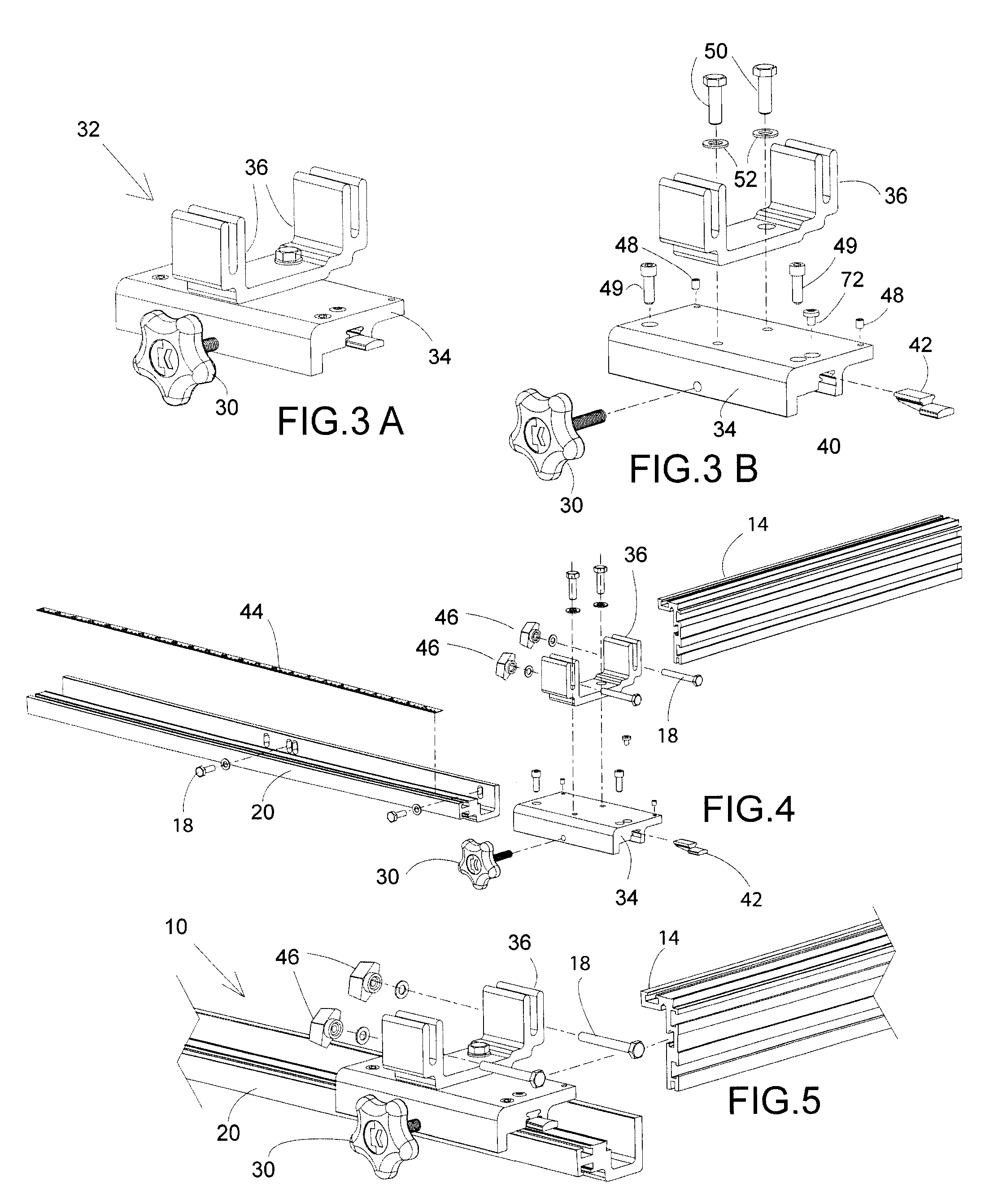
[0134]FIG. 3A is a perspective view of the fence bracket assembly 32 of the rip fence with the adapter mount 36 bolted to the top of the clamp block 34. The fence bracket assembly 32 is secured to the various rail designs of the system by tightening the knob 30, or by using a different fastener such as a cam lever.

[0135]FIG. 3B is an exploded perspective view of the rip fence showing that the adapter mount 36 is bolted to the clamp bracket ...


PUM

PropertyMeasurementUnit
Thicknessaaaaaaaaaa
Angleaaaaaaaaaa
Sizeaaaaaaaaaa

Abstract

A universal machinery fence system includes an L-shaped fence or a box shaped fence and clamp block which clamps to a rail extrusion with a half dovetail on the front on the edge of a table saw, band saw, shaper, router table, mortiser, or other woodworking or metal working machines. A U-shaped front rail is provided for attaching the fence to the cast iron table of a table saw, shaper, or band saw. The band saw fence U-shaped rail is predrilled to fit the table fence mounting holes of the most popular 14″ band saws. Optional extruded front rails are also provided for attaching the fence to shop made 0.750″ tables such as used on a drill press. Also provided is a fence rail extrusion for mounting the fence on the front and back of the popular 1.125″ size router table. An optional extruded front rail which is adjustable in height is also provided for attaching the fence to shop made tables between 0.750″ and 1.5″ in thickness. A re-saw guide fitted to the fence extrusion has a convex surface for supporting a workpiece on edge allowing the operator to easily adjust for blade drift. An optional micro-adjuster allows the fence to move accurately in small increments. A router table with holes and slots allows the fence to be used to guide the workpiece in the router table mode and then be used to guide the router or a saw on top of the workpiece.

Description

CROSS-REFERENCE TO RELATED APPLICATION [0001] This claims the benefit of U.S. Provisional Patent Application No. 60 / 678,502 filed May 6, 2005.STATEMENT CONCERNING FEDERALLY SPONSORED RESEARCH OR DEVELOPMENT [0002] Not applicable. FIELD OF THE INVENTION [0003] This invention relates to shop made jigs and fixtures and machine fences for positioning, aligning, guiding, and / or holding a workpiece on metalworking or woodworking machines during a cutting, drilling, shaping, or other workpiece material removal operation. BACKGROUND OF THE INVENTION [0004] U.S. Pat. Nos. 5,337,641, 5,617,909, 5,768,966, and U.S. Patent Publication No. US2005 0056345 A1, the disclosures of which are hereby incorporated by reference, disclose improved jigs and fixtures for aligning, guiding, and / or holding a workpiece as it is worked, for example as it is cut, drilled, or routed. While the jigs and fixtures disclosed in U.S. Pat. Nos. 5,337,641, 5,617,909, 5,768,966, and U.S. Patent Publication No. US2005 005...

Claims


Application Information

Patent Timeline
IPC IPC(8): B26D7/02B26D7/01
CPCB23Q3/007B27B27/10B27B27/00Y10T83/727Y10T83/7647Y10T83/7607Y10T83/76
Inventor DUGINSKE, MARK A.
Owner KREG ENTERPRISES
Why Eureka
Try Eureka