Manifold assembly for feeding reactive precursors to substrate processing chambers

a technology of reactive precursors and manifolds, which is applied in the direction of coatings, chemical vapor deposition coatings, metallic material coating processes, etc., can solve the problems of large time consumption, less than adequate purging of immediately preceding precursors, and equipment not without its associated drawbacks

Inactive Publication Date: 2006-11-09
MICRON TECH INC
View PDF1 Cites 299 Cited by
  • Summary
  • Abstract
  • Description
  • Claims
  • Application Information

AI Technical Summary

Problems solved by technology

At least with atomic layer deposition, such equipment is not without its associated drawbacks, both in speed of operation and in producing desired ALD layers atop substrates.
The existing method with the above general...

Method used


Image

  • Manifold assembly for feeding reactive precursors to substrate processing chambers
  • Manifold assembly for feeding reactive precursors to substrate processing chambers
  • Manifold assembly for feeding reactive precursors to substrate processing chambers

Examples


Embodiment Construction

[0016] This disclosure of the invention is submitted in furtherance of the constitutional purposes of the U.S. Patent Laws “to promote the progress of science and useful arts” (Article 1, Section 8).

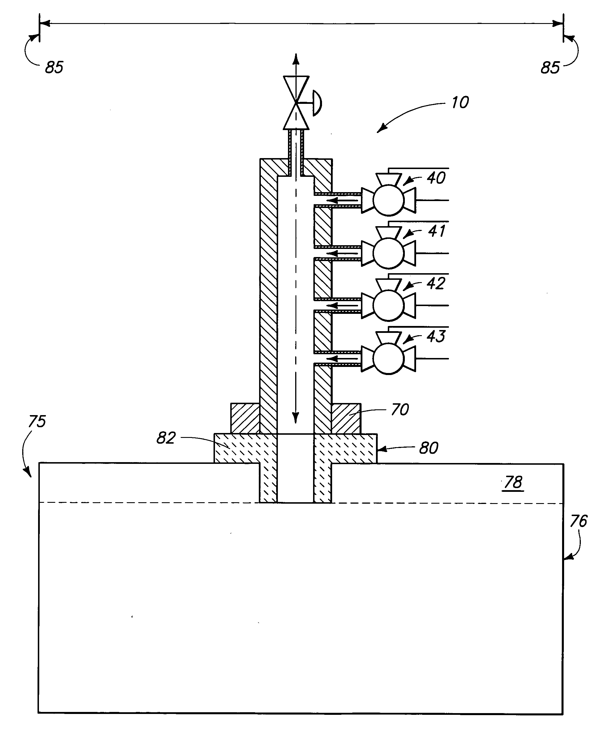
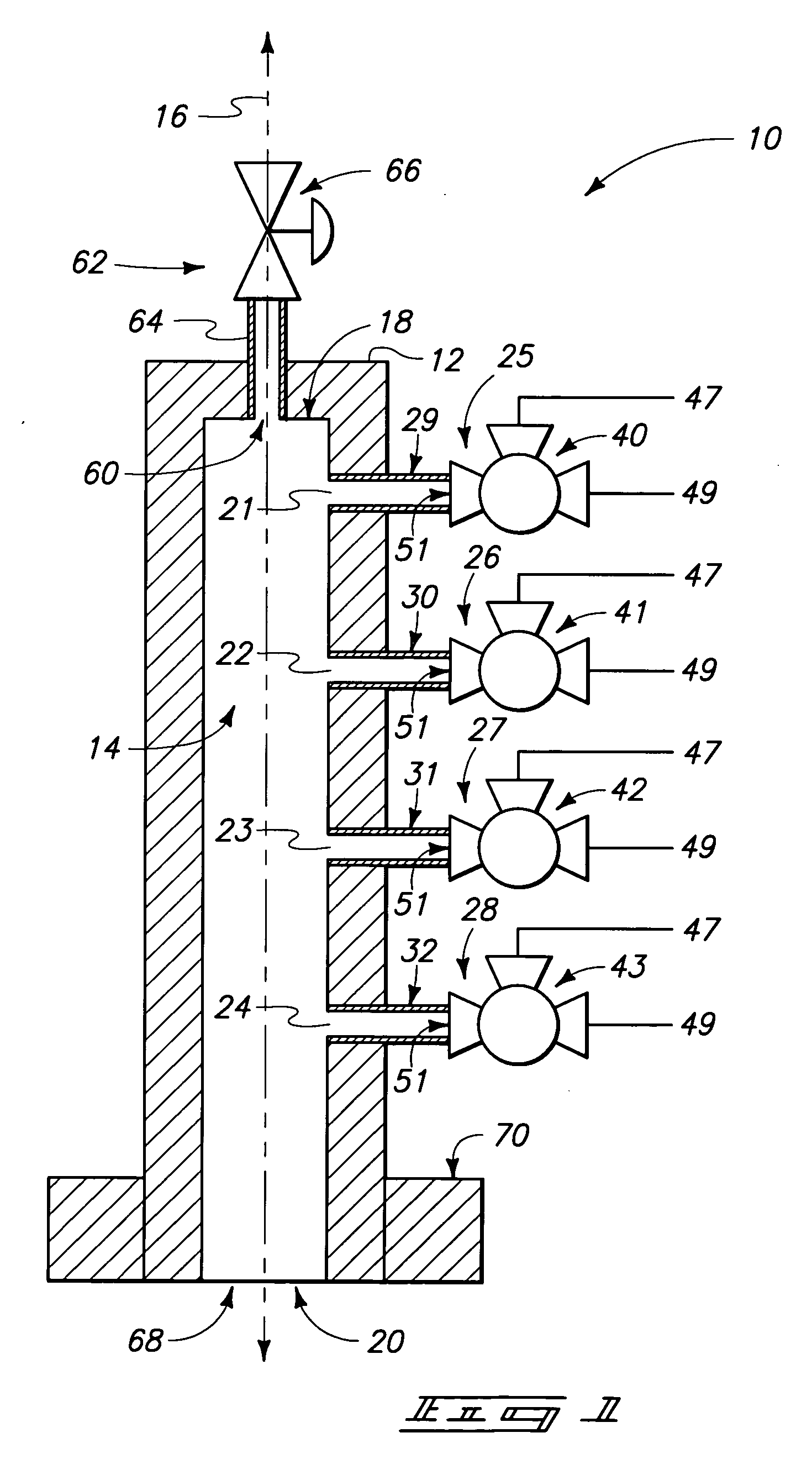
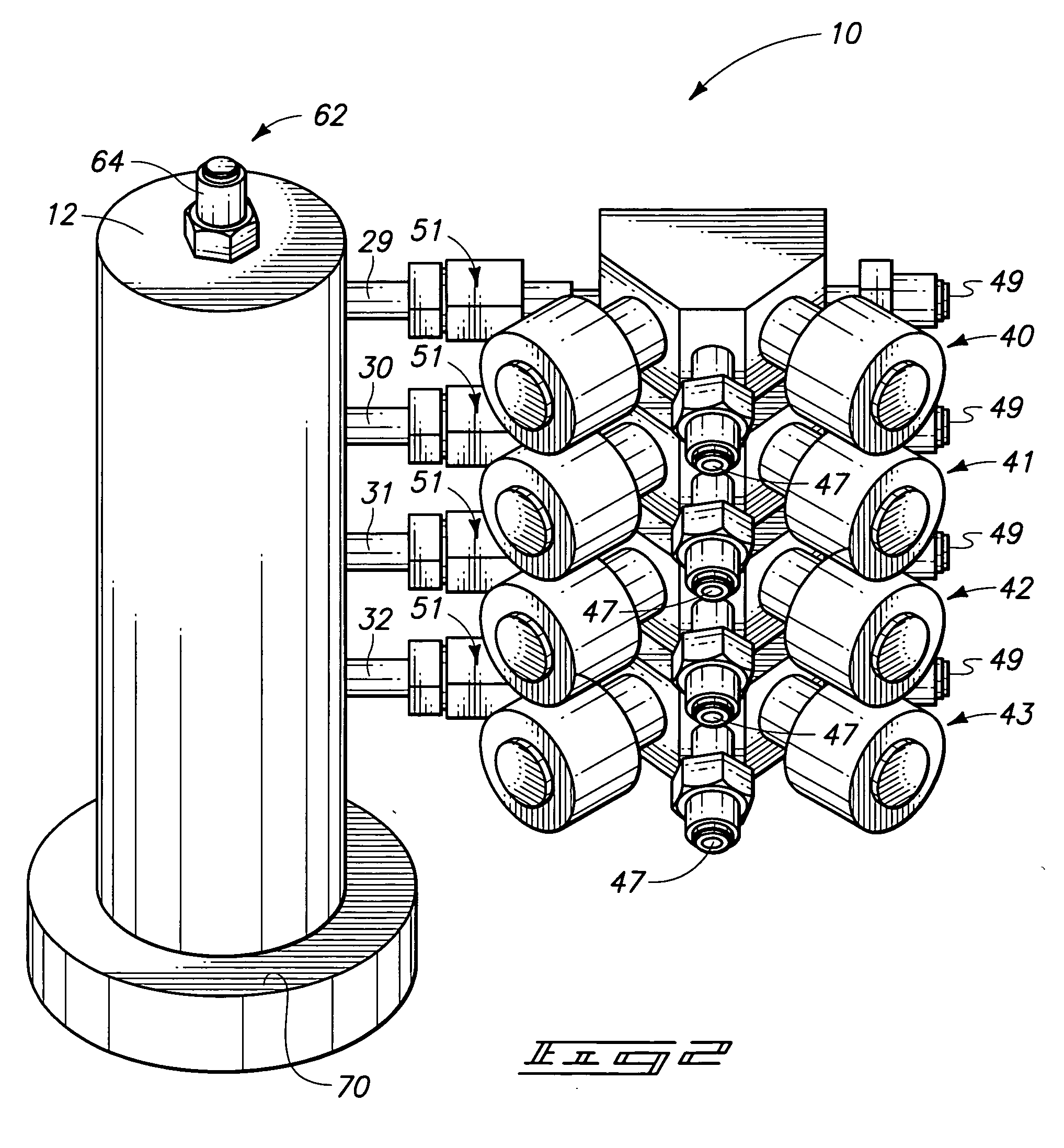
[0017] The invention encompasses a manifold assembly 10 for use in feeding reactive precursors to existing or yet-to-be developed substrate processing chambers. Exemplary such chambers include CVD chambers (including ALD) and etching chambers. In the context of this document, a “reactive precursor” is any substance which reacts with another precursor within the chamber or with something / anything else in the chamber. Referring initially to FIGS. 1 and 2, a preferred embodiment manifold assembly is indicated generally with reference numeral 10. FIG. 1 diagrammatically and conceptually illustrates a preferred embodiment implementation of the invention, with FIG. 2 perspectively showing a preferred exemplary reduction-to-practice structure, and by way of example only. Manifold assembly 10 i...


PUM

PropertyMeasurementUnit
Angleaaaaaaaaaa
Angleaaaaaaaaaa
Angleaaaaaaaaaa

Abstract

A reactive precursor feeding manifold assembly includes a body comprising a plenum chamber. A valve is received proximate the body and has at least two inlets and at least one outlet. At least one valve inlet is configured for connection with a reactive precursor source. At least one valve outlet feeds to a precursor inlet to the plenum chamber. A purge stream is included which has a purge inlet to the plenum chamber which is received upstream of the plenum chamber precursor inlet. The body has a plenum chamber outlet configured to connect with a substrate processing chamber. In one implementation, the plenum chamber purge inlet is angled from the plenum chamber precursor inlet. In one implementation, structure is included on the body which is configured to mount the body to a substrate processing chamber with the plenum chamber outlet proximate to and connected with a substrate processing chamber inlet.

Description

RELATED PATENT DATA [0001] This patent resulted from a continuation application of U.S. patent application Ser. No. 10 / 087,558 which was filed Feb. 28, 2002.TECHNICAL FIELD [0002] This invention relates to apparatus used to feed reactive precursors to substrate processing chambers, for example etching chambers and deposition chambers. BACKGROUND OF THE INVENTION [0003] Semiconductor processing in the fabrication of integrated circuitry involves the deposition of layers on semiconductor substrates. Exemplary processes include physical vapor deposition (PVD) and chemical vapor deposition (CVD). In the context of this document, “CVD” includes any process, whether existing or yet-to-be developed, where one or more vaporized chemicals is fed as a deposition precursor for reaction and adherence to a substrate surface. By way of example only, one such CVD process includes atomic layer deposition (ALD). With ALD, successive mono-atomic layers are adsorbed to a substrate and / or reacted with ...

Claims


Application Information

Patent Timeline
IPC IPC(8): H01L21/306C23C16/44C23C16/455
CPCC23C16/4408C23C16/45561C23C16/455
Inventor DANDO, ROSS S.CARPENTER, CRAIG M.DERDERIAN, GARO J.
Owner MICRON TECH INC
Why Eureka
Try Eureka