Control device for fluid dispenser

a control device and fluid dispenser technology, applied in the direction of liquid transfer devices, mechanical devices, transportation and packaging, etc., can solve the problems of hand not being micro-adjusted relative, thumb injury, etc., and achieve the effect of easy control of a spraying gun or facility

Inactive Publication Date: 2006-11-09
GUO WEN LI
View PDF11 Cites 15 Cited by
  • Summary
  • Abstract
  • Description
  • Claims
  • Application Information

AI Technical Summary

Benefits of technology

[0008] The primary objective of the present invention is to provide a control device including a simplified configuration for easily controlling a spraying gun or facility or a fluid dispenser or other nozzles.

Problems solved by technology

Normally, the handle is depressed toward a grip of the hose nozzle body while operating the typical fluid dispensers, such that the handle may not be micro-adjusted relative to the grip of the hose nozzle body while operating the typical fluid dispensers.
However, the side portions of the thumb of the user may be hurt by the nail of the thumb while depressing or rotating the actuating member relative to the tubular body with the side portions of the thumb of the user.

Method used


Image

  • Control device for fluid dispenser
  • Control device for fluid dispenser
  • Control device for fluid dispenser

Examples


Embodiment Construction

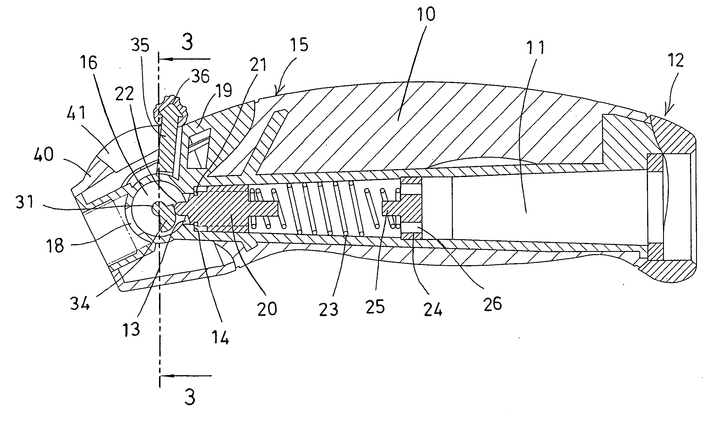
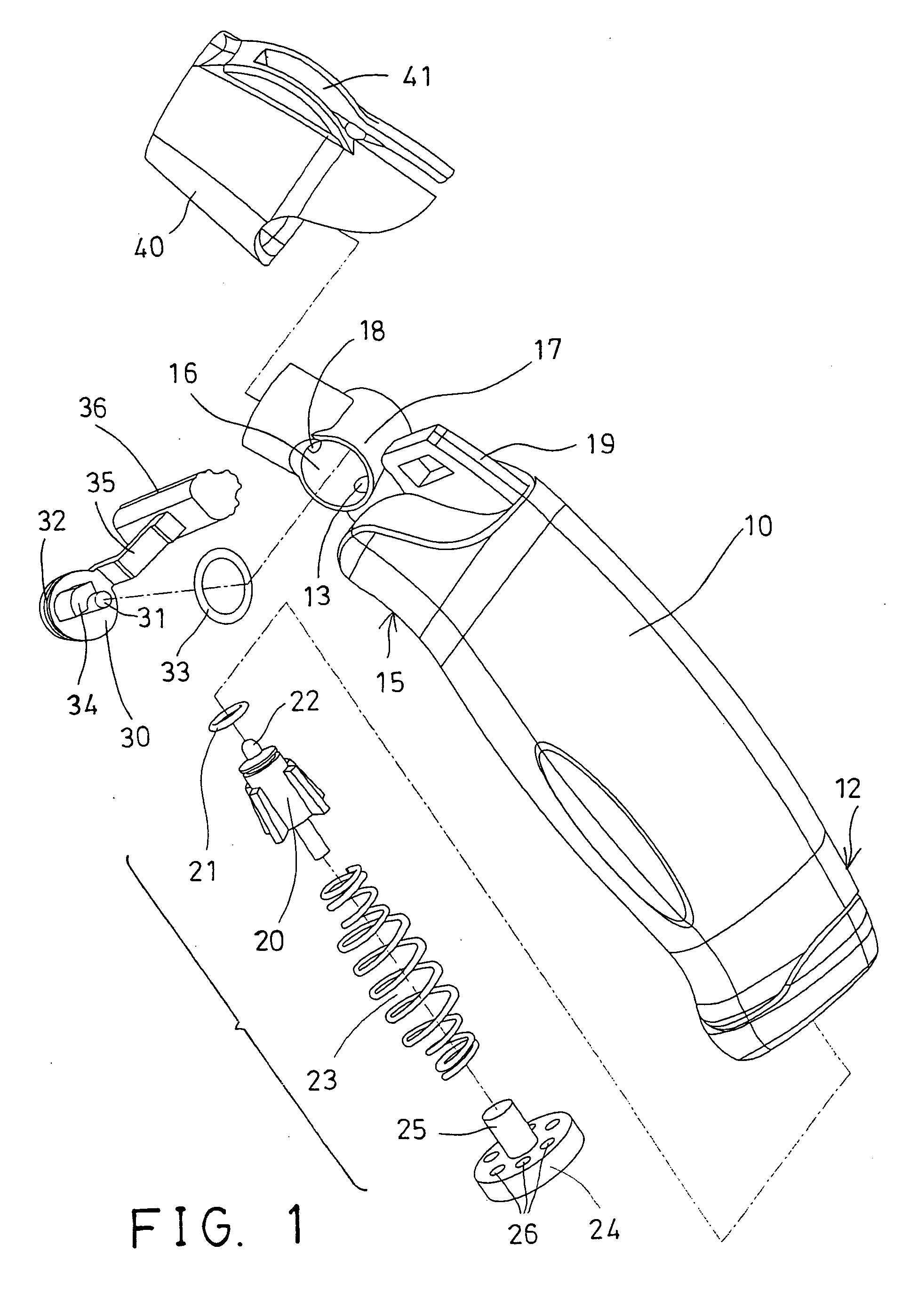
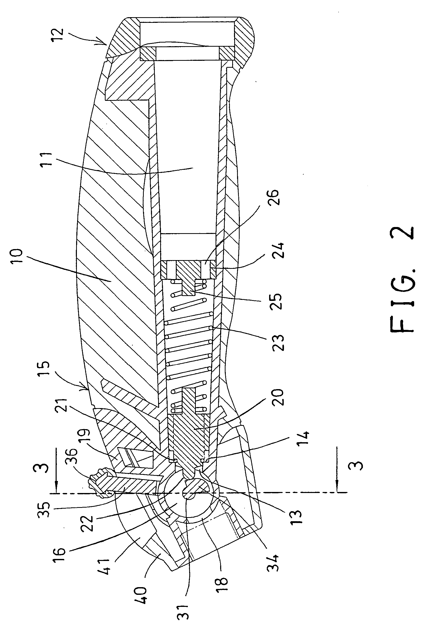
[0022] Referring to the drawings, and initially to FIGS. 1-4, a fluid dispenser in accordance with the present invention comprises a dispenser body or handle 10 including a bore 11 formed therein, and including one end 12 for coupling to a water reservoir, in order to receive the water and to allow the water to flow into the bore 11 thereof, and including an opening 13 and a valve seat 14 formed or provided on the other end 15 thereof, for the water to flow out of the handle 10.

[0023] A valve member 20 is slidably received in the bore 11 of the handle 10, and includes a sealing ring 21 attached to one end thereof, for engaging with the valve seat 14 of the handle 10, and for selectively enclosing or blocking or opening the opening 13 of the handle 10. The valve member 20 includes an extension 22 extended from the one end thereof, and extended out through the opening 13 of the handle 10 (FIGS. 2 and 5-8). A spring biasing means or a spring member 23 may be engaged onto the valve mem...


PUM


Abstract

A fluid dispenser includes a handle having a valve seat and a compartment, a valve member slidably received in the handle, for selectively engaging with the valve seat of the handle, to selectively enclose and block the bore of the handle. A spring member may bias the valve member to engage with the valve seat of the handle. A control member is rotatably engaged in the compartment of the handle, and includes an actuator for engaging with the valve member, and for selectively moving the valve member away from the valve seat of the handle when the control member is rotated relative to the handle. The control member includes an axle rotatably secured to a casing of the handle.

Description

BACKGROUND OF THE INVENTION [0001] 1. Field of the Invention [0002] The present invention relates to a trigger or control device, and more particularly to a trigger or control device having a simplified configuration for easily controlling a spraying gun or spraying facility or fluid dispenser or the like. [0003] 2. Description of the Prior Art [0004] Typical spraying guns or facilities comprise a trigger or control device attached to a handle thereof, for triggering or controlling the water to flow into the spraying guns or facilities, or to stop the water from flowing into the spraying guns or facilities, and normally including a hand grip pivotally attached or coupled to the handle thereof, to control the spraying guns or facilities. [0005] For example, U.S. Pat. No. 4,534,512 to Chow et al. discloses one of the typical fluid dispensers comprising a handle pivotally mounted on the hose nozzle body and adapted for movement between a no flow position and a full open position. Norma...

Claims


Application Information

Patent Timeline
Patent Type & Authority Applications(United States)
IPC IPC(8): B05B9/08B67D7/36
CPCF16K35/025B05B1/3013
Inventor GUO, WEN LI
Owner GUO WEN LI
Why Eureka
Try Eureka