
Computer system, method, and program product for performing a data access from low-level code

Active Publication Date: 2006-06-20
ORACLE INT CORP
View PDF6 Cites 13 Cited by
  • Summary
  • Abstract
  • Description
  • Claims
  • Application Information

AI Technical Summary

Benefits of technology

[0021]A typical situation where such an approach can be applied arises where the low-level code comprises a trap routine, and it is desired to instrument this routine. This would normally require at least one free register to function as a pointer to an area where the instrumentation output is to be stored. This has previously prevented insertion of instrumentation at arbitrary points in the trap routine code, without the need for extra (and risky) effort to make available the desired register. Indeed, standard trap instrumentation typically requires two registers to operate a circular buffer for output, thereby exacerbating the problem.
[0022]In contrast, the approach described herein allows such a RISC processor to reliably and efficiently address a region of memory without altering the contents of any program-visible register. This is particularly valuable for RISC processors that have very limited facilities for addressing via immediate data (i.e. they generally require that the write address for a store operation is made available to a processor in a register). It is also of great benefit for contexts such as trap handling, where very few assumptions can be made about register and memory availability.
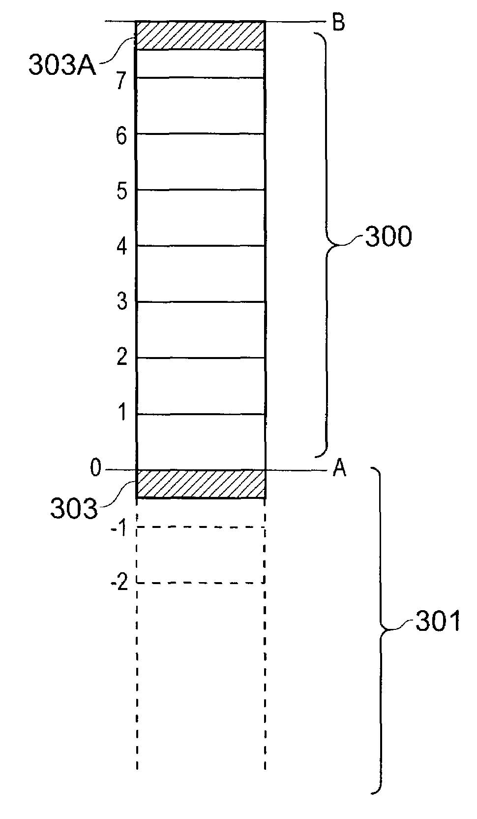
[0025]The allocation of the page or pages in the memory region are locked in a translation lookaside buffer (TLB) in order to ensure that their mappings to the corresponding physical memory locations are always available. This helps to ensure that accessing the allocated region does not result in any (secondary) traps.
[0027]In one embodiment, the allocated region of memory is used for directly storing output from trap instrumentation and other low-level code as and when required, thereby avoiding any risk of altering register state. In another embodiment, further flexibility may be obtained by using the allocated region to save initial values from at least two registers. This then allows these registers to be used to define a circular buffer or any other desired memory structure for use by the low-level code (it will be appreciated that such a memory structure does not have to be within the allocated region, but could be at any other suitably available location in the address space). Once the low-level code has completed, the initial values of the registers can be then restored from the saved values in the allocated memory region to allow the system to continue processing as before. In this context, the allocated region has served in effect as a fast register stash, without the complexity or overhead of having to generate a stack frame.
[0029]In one embodiment of the present invention, the allocated region for each CPU is used for storing information particular to that CPU, such as the address of the record having status data for that CPU. This then allows the status information to be accessed directly and quickly, avoiding the need for any hardware lookup and subsequent conversion of the CPU identity into the address of the relevant record. Such a performance benefit can potentially more than compensate for a single locked entry in the TLB.

Problems solved by technology

Indeed, standard trap instrumentation typically requires two registers to operate a circular buffer for output, thereby exacerbating the problem.

Method used


Image

  • Computer system, method, and program product for performing a data access from low-level code
  • Computer system, method, and program product for performing a data access from low-level code
  • Computer system, method, and program product for performing a data access from low-level code

Examples


Embodiment Construction

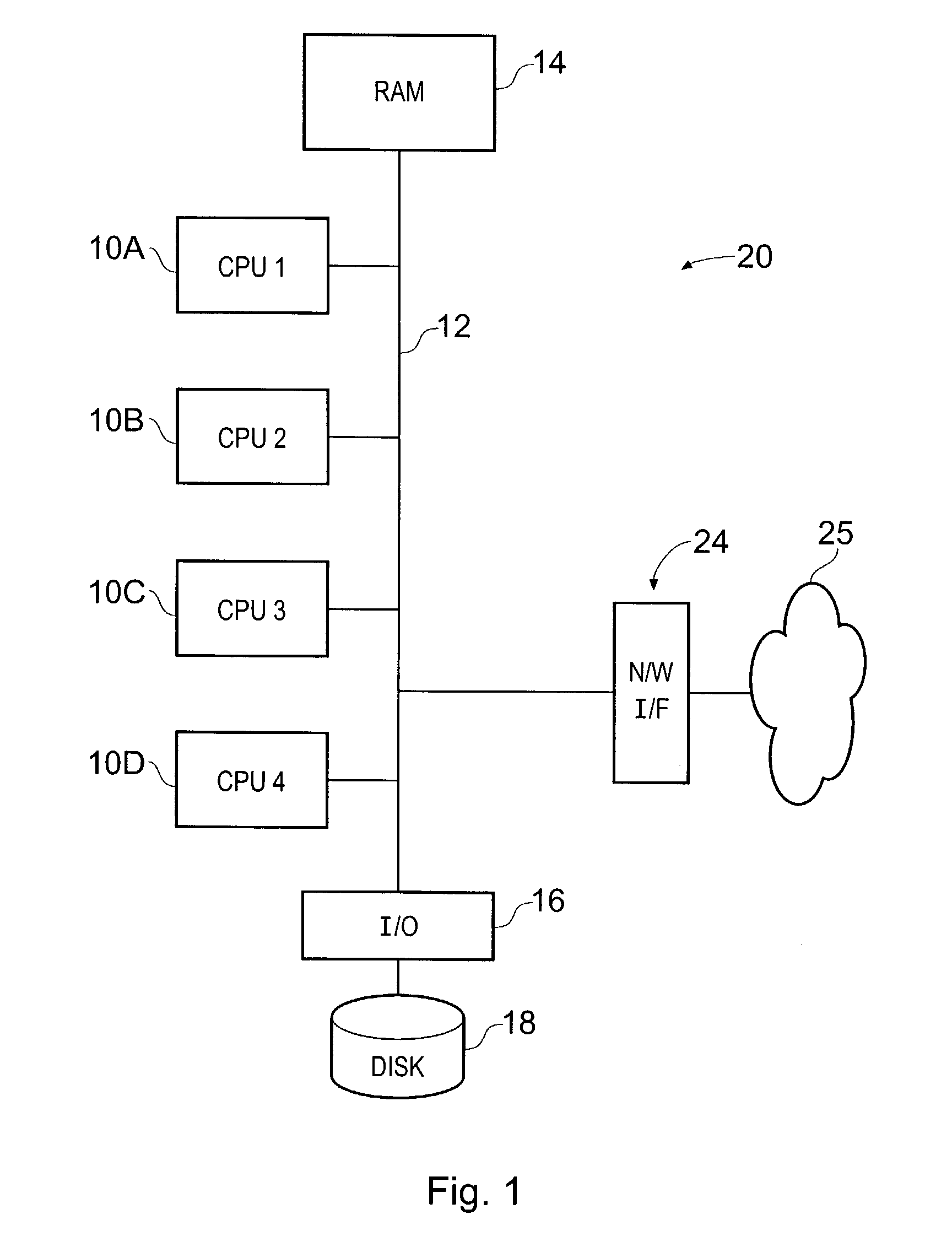
[0042]FIG. 1 is a simplified schematic diagram of a multi-processor system 20 in accordance with one embodiment of the present invention. System 20 includes four CPUs 10A, B, C and D (although of course more or fewer CPUs may be included in other embodiments). Each of these includes a processor (such as a SPARC processor from Sun Microsystems Inc), together with associated registers, cache memory, and other components (not shown in FIG. 1). The CPUs 10 are interconnected by bus 12, which also links them to shared physical memory, RAM 14. This is shared in the sense that generally any CPU can access any particular piece of RAM. The CPUs 10 are also attached via interface 16 to external disk storage 18. This may typically be provided by multiple disk drives, for example as arranged into a redundant array of inexpensive drives (RAID) architecture. Bus 12 is further connected to network interface 24 in order to allow system 20 to communicate via network 25.

[0043]Note that a wide variety...


PUM


Abstract

A computer system includes a register that is configured to contain a zero value. In response to a predetermined occurrence on the computer system, such as a hardware interrupt, the computer system launches a trap routine. This routine generates output data that needs to be stored within the memory space of the computer system. In order to write out this data from within the trap routine, a desired target address is specified as a negative offset from the zero value stored in the register. This avoids the need to have to locate another (unused) register in which to store the write address.

Description

FIELD OF THE INVENTION[0001]The present invention relates to a computer system, and in particular to a method for performing a data access from low-level code, such as a trap routine, running on the computer system.BACKGROUND OF THE INVENTION[0002]Many modem operating systems are built around a kernel, which provides a core set of functionality and services to allow programs to run on the computer hardware. The kernel includes code routines for handling traps. The operating system invokes such a routine (known as a trap routine) if an event occurs that is in some way unexpected or unanticipated.[0003]There are a relatively wide variety of circumstances that can lead to a trap routine being called. One example is a page fault, when a process attempts to access a virtual address, and the memory management unit (MMU) does not currently contain a mapping from this virtual address to a real physical memory location. This can occur if there is not enough room within the MMU, more particul...

Claims


Application Information

Patent Timeline
IPC IPC(8): G06F12/00G06F9/30G06F9/355G06F11/34
CPCG06F9/30101G06F9/355G06F2201/865G06F11/3476G06F11/3466
Inventor ALDERSON, JOHN
Owner ORACLE INT CORP
Learn More