Liquid dispenser

a dispenser and liquid technology, applied in the field of liquid dispensers, can solve the problems of general difficulty, undesirable leakage, valve malfunction, etc., and achieve the effects of convenient operation, simple construction, and more controllable discharge facilities

Inactive Publication Date: 2008-10-30
LECUYER SYLVAIN +1
View PDF7 Cites 6 Cited by
  • Summary
  • Abstract
  • Description
  • Claims
  • Application Information

AI Technical Summary

Benefits of technology

[0006]An advantage of the present invention is that the liquid dispenser is of simple construction and easy operation.
[0007]Another advantage of the present invention is that the liquid dispenser gives a more controlled discharge facility, and significantly reduces spillage.
[0008]According to a first aspect of the present invention there is provided a liquid dispenser comprising:
[0009]a container defining a liquid holding chamber having two ends, and surrounding walls integral with and interconnecting the said ends;
[0010]a port defined at one end of the container and a liquid discharge outlet defined at the other end of the container;
[0011]a tapering spout provided externally of the container and extending therefrom to define the discharge outlet, the spout defining a valve seating section therewithin;

Problems solved by technology

One of the problems associated with conventional dispensers is their use in filling other receptacles or reservoirs without spilling the liquids.
Difficulty is generally encountered because of the distance needed to be bridged when upturning the dispenser to align its discharge outlet with the relevant charging reception port.
Necessarily spillage occurs even when using a funnel or spout, especially in windy weather conditions or the like, the weight of the dispenser being another contributory factor to the problem.
One of the perceived disadvantages of this proposal is the lack of certainty associated with the effective reseating of the valve since continuity of linear movement of the valve stem is not guaranteed, thus giving rise to the possibility of a malfunction of the valve accompanied by undesirable leakage through the discharge outlet of the container.

Method used


Image

  • Liquid dispenser
  • Liquid dispenser
  • Liquid dispenser

Examples


Embodiment Construction

[0030]With reference to the annexed drawings the preferred embodiment of the present invention will be herein described for indicative purpose and by no means as of limitation.

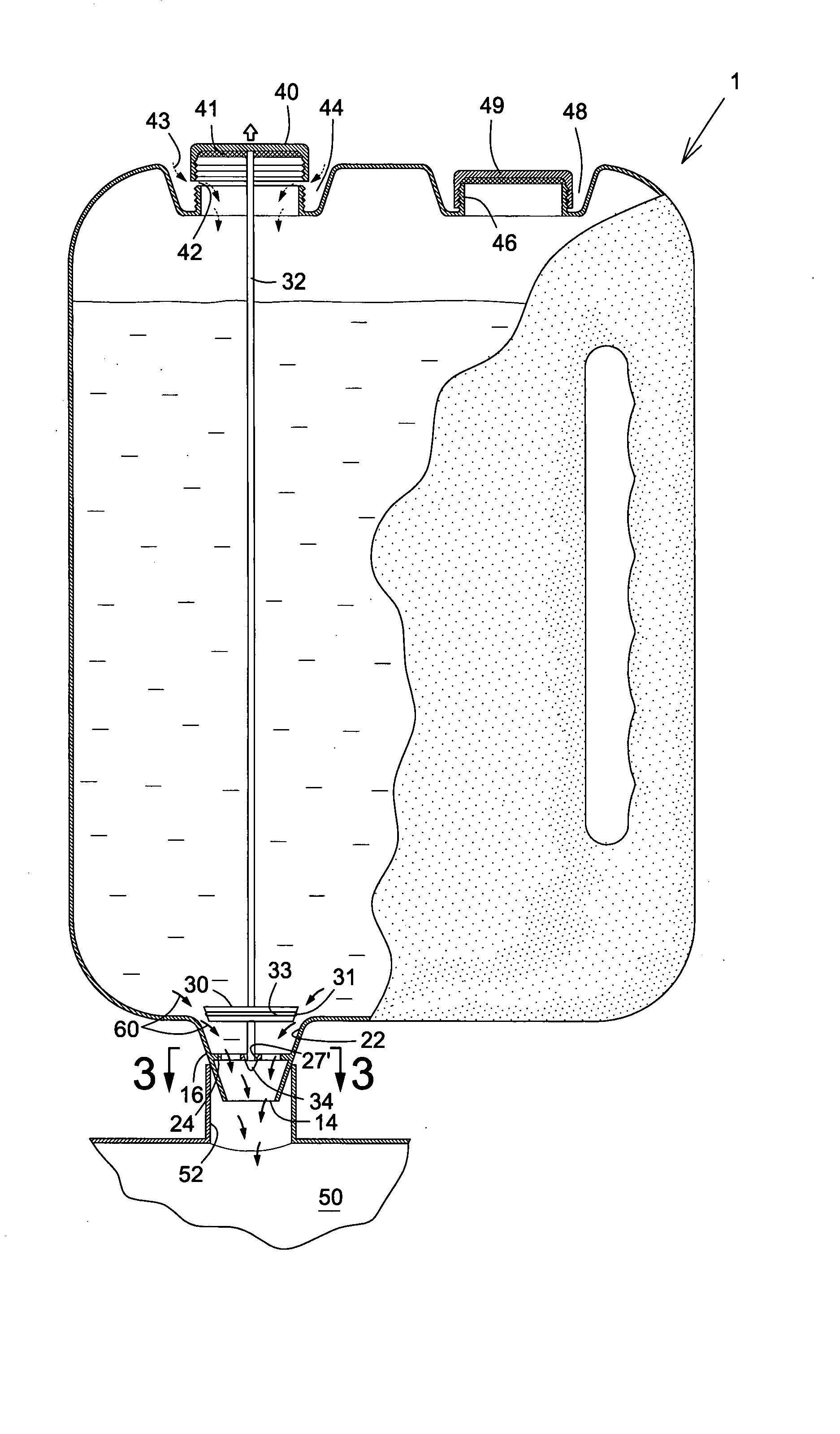
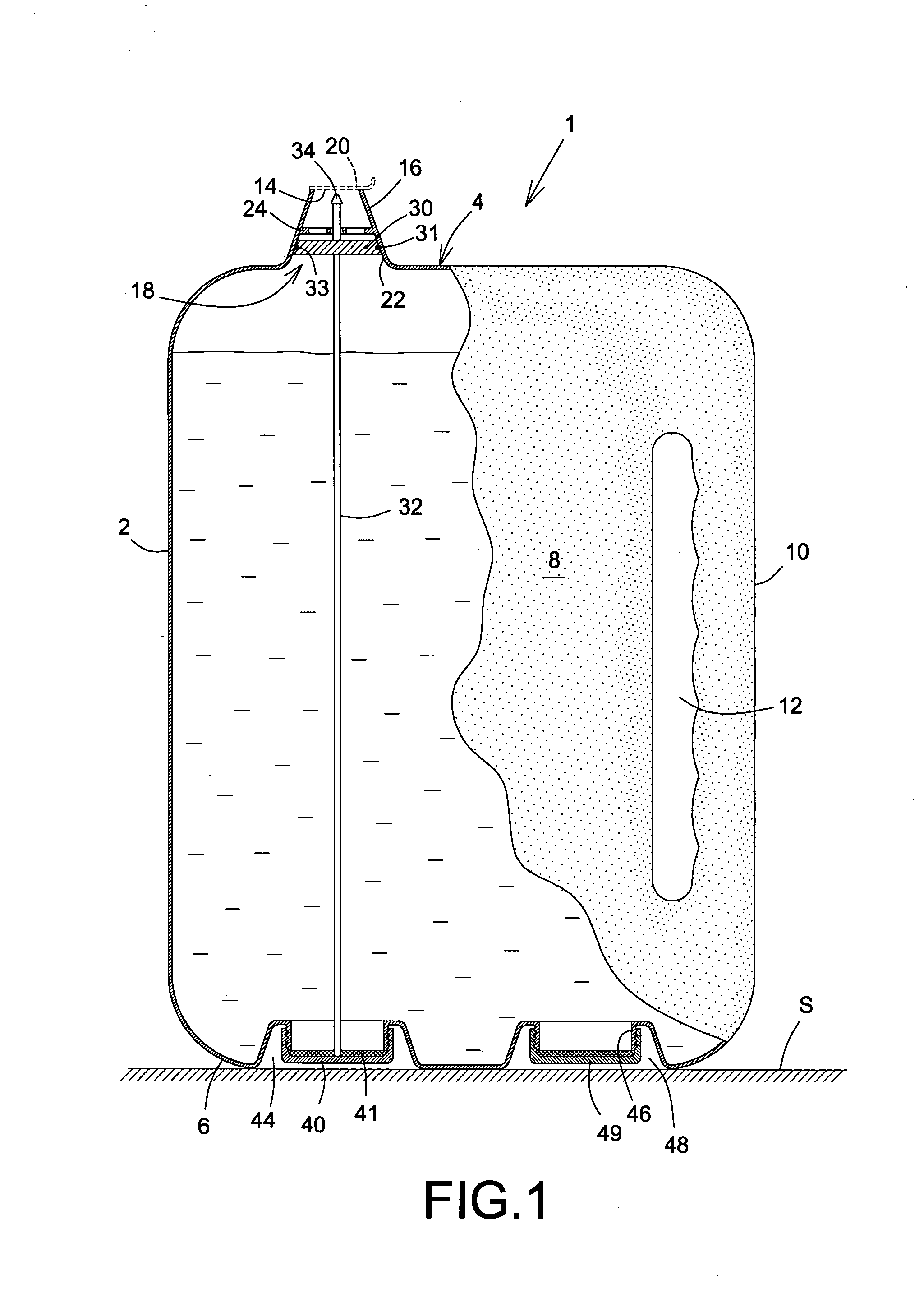
[0031]In FIGS. 1 and 2 there is shown a liquid dispenser 1 comprising a container 2 typically molded from a plastics material having two ends 4, 6 with sides 8, 10. The container is provided with an integral hollow handle 12 in at least one of the side walls 10.

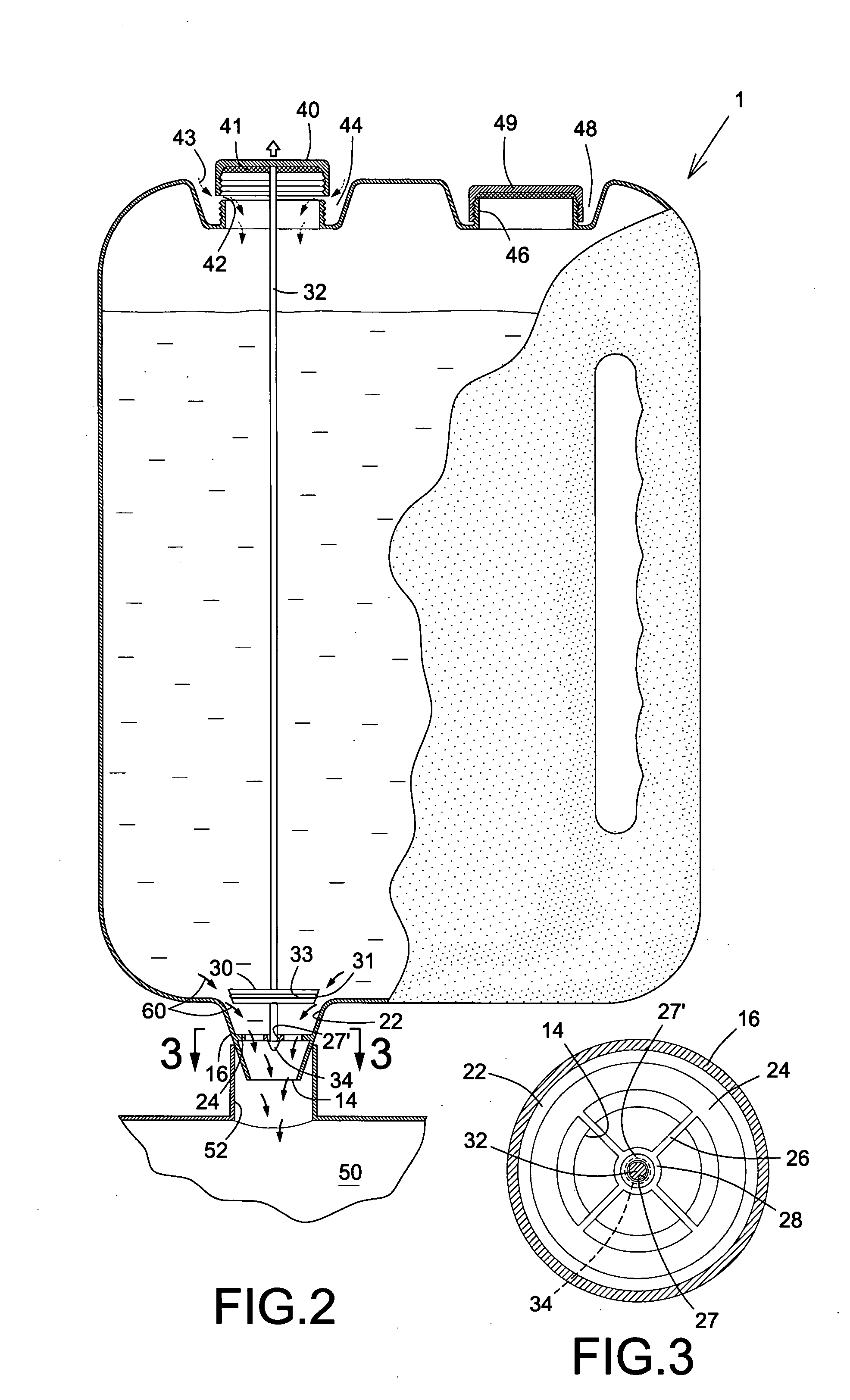
[0032]A discharge outlet 14 is formed at the narrower end of a spout 16 extending from an opening 18 in end 4 of the container 2. A temporary foil seal 20 is shown covering the outlet 14 and is intended for removal and disposal upon first usage of the dispenser 1. The spout 16 defines therewithin a valve seating section 22 and also accommodates in fixed manner a discharge grid 24, which is annular and has a spider 26 with a central apertured boss 28.

[0033]A valve member 30 is carried on a valve stem 32 extending essentially the full depth of the contain...


PUM


Abstract

A liquid dispenser includes a container having a valved discharge outlet, the valve being actuable remotely by a screw cap of the container, which carries the valve stem. The valve stem is guided in usage during its linear travel between open and closed modes, the guidance being provided in the region of the discharge outlet by an apertured centre boss of a discharge grid.

Description

FIELD OF THE INVENTION[0001]The present invention relates to a liquid dispenser and has particular reference to such a dispenser suitable for containing a liquid intended to be poured into a receptacle or reservoir by way of replenishment. The invention has especial, but not exclusive, reference for such a dispenser used for recharging automobile reservoirs with fresh liquids, for example water for the radiator and the engine cooling system, the windshield washer fluid for the appropriate reservoir, and others.BACKGROUND OF THE INVENTION[0002]One of the problems associated with conventional dispensers is their use in filling other receptacles or reservoirs without spilling the liquids. Difficulty is generally encountered because of the distance needed to be bridged when upturning the dispenser to align its discharge outlet with the relevant charging reception port. Necessarily spillage occurs even when using a funnel or spout, especially in windy weather conditions or the like, the ...

Claims


Application Information

Patent Timeline
Patent Type & Authority Applications(United States)
IPC IPC(8): B67D3/00B67D7/54B67D7/36B67D7/42
CPCB65D1/06B65D47/248
Inventor L'ECUYER, SYLVAIN
Owner LECUYER SYLVAIN
Why Eureka
Try Eureka