
Resonator

a resonator and resonator technology, applied in the field of resonators, can solve the problems of unclear guidance on how to improve free-fall resistance, and achieve the effect of excellent free-fall resistance and highly reliable resonators

Inactive Publication Date: 2006-11-09
TDK CORPARATION
View PDF10 Cites 0 Cited by
  • Summary
  • Abstract
  • Description
  • Claims
  • Application Information

AI Technical Summary

Benefits of technology

[0010] The present invention was created based on such technical problems, wherein it is an object thereof to provide a resonator having excellent free-fall resistance.
[0012] The resonator according to the present invention is particularly effective when the substrate has a structure that comprises a terminal electrode wherein the piezoelectric ceramic resonator is supported at both ends on the substrate and in electrical continuity with the vibrating electrode via a conductive member. Thus, the present invention also encompasses a structure which supports a piezoelectric ceramic resonator on the substrate via some other member.
[0015] According to the present invention, a resonator can be provided which comprises a piezoelectric ceramic resonator having excellent free-fall resistance. Moreover, according to the present invention, if the maximum elastic energy U of the piezoelectric ceramic resonator is understood, a highly reliable resonator can be provided without conducting an actual drop test.

Problems solved by technology

Therefore, since mechanical strength as required by a product specification is not itself a physical property, in the past the guidelines for how free-fall resistance could be improved were unclear.

Method used


Image

  • Resonator
  • Resonator
  • Resonator

Examples


Embodiment Construction

[0025] The present invention will now be described in more detail based on the embodiments.

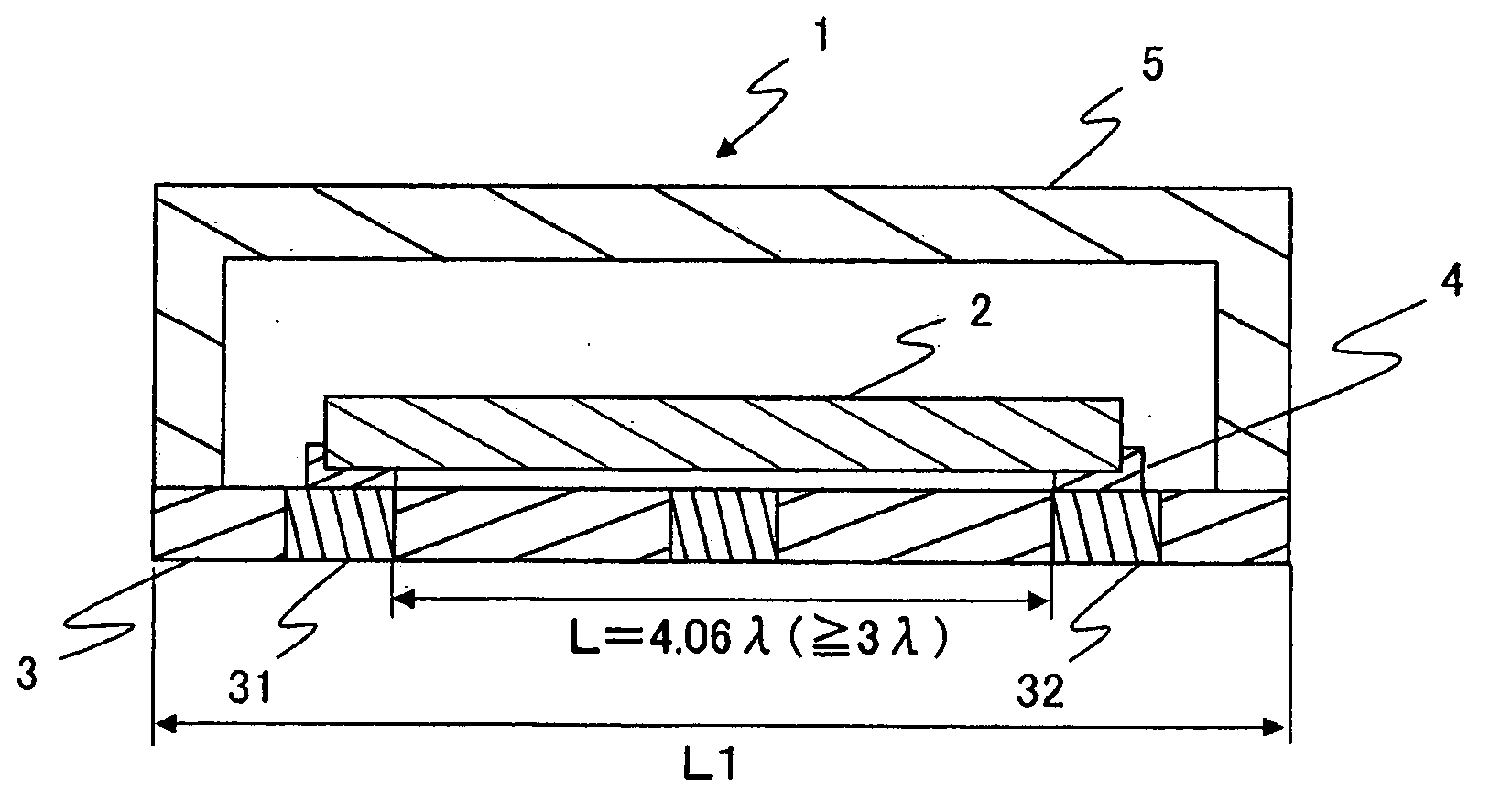
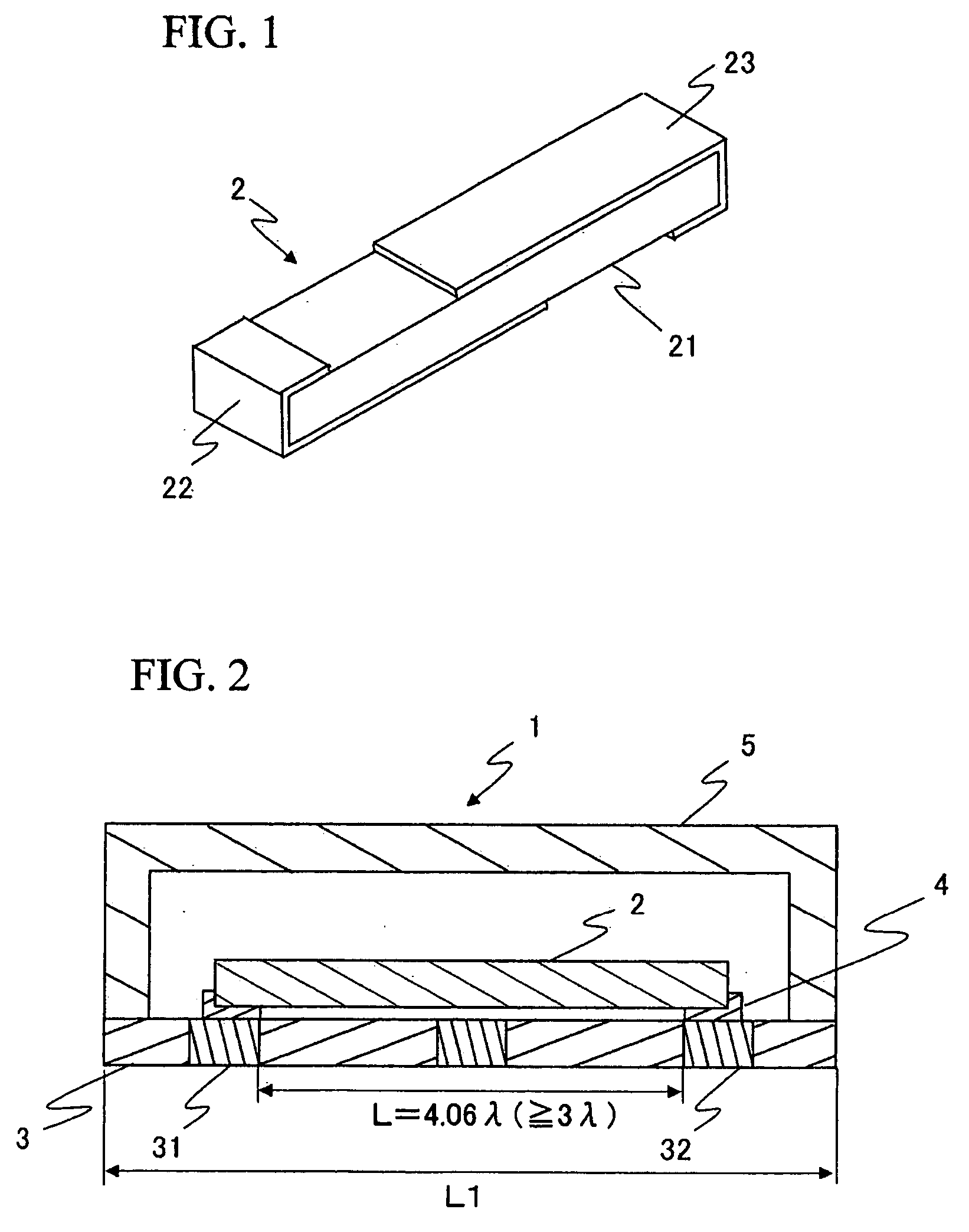
[0026]FIG. 2 is a cross-sectional view for explaining the resonator 1 according to the present embodiment. The basic structure of the resonator 1 illustrated in FIG. 2 has been explained in the section entitled “Description of the Related Art”, and thus repetitive explanation will be omitted here.

[0027] The present invention is characterized in that the piezoelectric ceramic resonator 2, which is a constituent feature of the resonator 1, satisfies the condition U≧0.88×H+20.28 wherein U=maximum elastic energy (kJ / m3), and H=drop height (m) (H>1). By satisfying this condition, the occurrence of defects such as chips or cracks in the piezoelectric ceramic resonator 2 can be prevented when the resonator 1 is dropped from a certain height. The drop tests from which this condition was derived will now be explained.

[0028] Specimens comprising the following piezoelectric ceramics were subjected to ...


PUM

PropertyMeasurementUnit
thicknessaaaaaaaaaa
temperatureaaaaaaaaaa
heightaaaaaaaaaa

Abstract

There is provided a resonator having a piezoelectric ceramic resonator which has excellent free-fall resistance. The resonator comprises a piezoelectric ceramic resonator 2 with a vibrating electrode formed, and a substrate 3 which supports the piezoelectric ceramic resonator 2, wherein the piezoelectric ceramic resonator 2 satisfies the condition of U≧0.88×H+20.28, wherein U=maximum elastic energy (kJ / m3) per unit volume, and H=drop height (m) (H>1). The present invention can be applied to a resonator 1, wherein the substrate 3 has terminal electrodes 31, 32, and the piezoelectric ceramic resonator 2 is in electrical continuity with the vibrating electrode and is supported on the substrate 3 at both ends via a conductive stator 4.

Description

BACKGROUND OF THE INVENTION [0001] 1. Field of the Invention [0002] The present invention relates to a resonator employing a piezoelectric ceramic resonator, and particularly relates to a resonator having excellent free-fall resistance. [0003] 2. Description of the Related Art [0004] Piezoelectric resonating parts (resonators) which employ a piezoelectric ceramic resonator are known as resonators that attain an oscillating frequency. As illustrated in FIG. 1, a piezoelectric ceramic resonator 2 is constituted by forming a pair of vibrating electrodes 22, 23 on the front and back main faces of a polarized piezoelectric ceramic substrate 21, so that vibrations are trapped in the vicinity of the pair of vibrating electrodes 22, 23. As illustrated in FIG. 2, a resonator 1 employing this piezoelectric ceramic resonator 2 comprises a substrate 3 and a cap 5. The substrate 3 has a strengthening function, and for example can be constituted from a ceramic such as steatite (MgO.SiO2), alumina...

Claims


Application Information

Patent Timeline
Patent Type & Authority Applications(United States)
IPC IPC(8): H01L41/187C04B35/493H01L41/09H01L41/22H01L41/257H01L41/313H01L41/39H03H9/17
CPCH03H3/02H03H9/02031H03H9/177H03H9/1035H03H9/1014
Inventor AZUMA, TOMOHISAHIROSE, MASAKAZUSUZUKITANIWAKI, KOUJI
Owner TDK CORPARATION
Learn More