Accurate persistent nodes

a persistent node and accurate technology, applied in the field of timing circuits, can solve the problems of inability to accurately control the timing of these circuits and varying by factors of 10 or mor

Active Publication Date: 2006-11-09
ZEST LABS INC
View PDF32 Cites 24 Cited by
  • Summary
  • Abstract
  • Description
  • Claims
  • Application Information

AI Technical Summary

Benefits of technology

[0028] The solution proposed herein avoids such things as having to count each tag at a dock door twice. In order to avoid counting every tag twice, the system needs to know that the tag will revert to the A-state, and precisely when it will revert to the A-state. If it is known for sure that the tag will revert to the A-state in about 500 ms, then there is no need to count each tag twice, because the system can make certain that all tags will be in the A-state. Because all tags are in the A-state, the reader need only count the tags that are in the A-state. This is not only more reliable than results obtained with heretofore known persistent nodes, but allows an accurate count in half the time of the current state of the art method.

Problems solved by technology

While some success has been achieved with ultra-long-time-constant RC-type circuits, the timing of these circuits is impossible to control accurately and vary by factors of 10× or more.

Method used


Image

  • Accurate persistent nodes
  • Accurate persistent nodes
  • Accurate persistent nodes

Examples


Embodiment Construction

[0038] The following description is the best embodiment presently contemplated for carrying out the present invention. This description is made for the purpose of illustrating the general principles of the present invention and is not meant to limit the inventive concepts claimed herein.

[0039] The following specification describes systems and methods for providing an accurate persistent node that has a very predictable time constant that is independent of whether power is interrupted. Accordingly, the reader need only periodically issue select commands, and the tag will not revert to another state (e.g., will stay asleep). However, if the reader does not issue a command, the tag will revert after some predetermined time period, e.g., about 200-2000 ms.

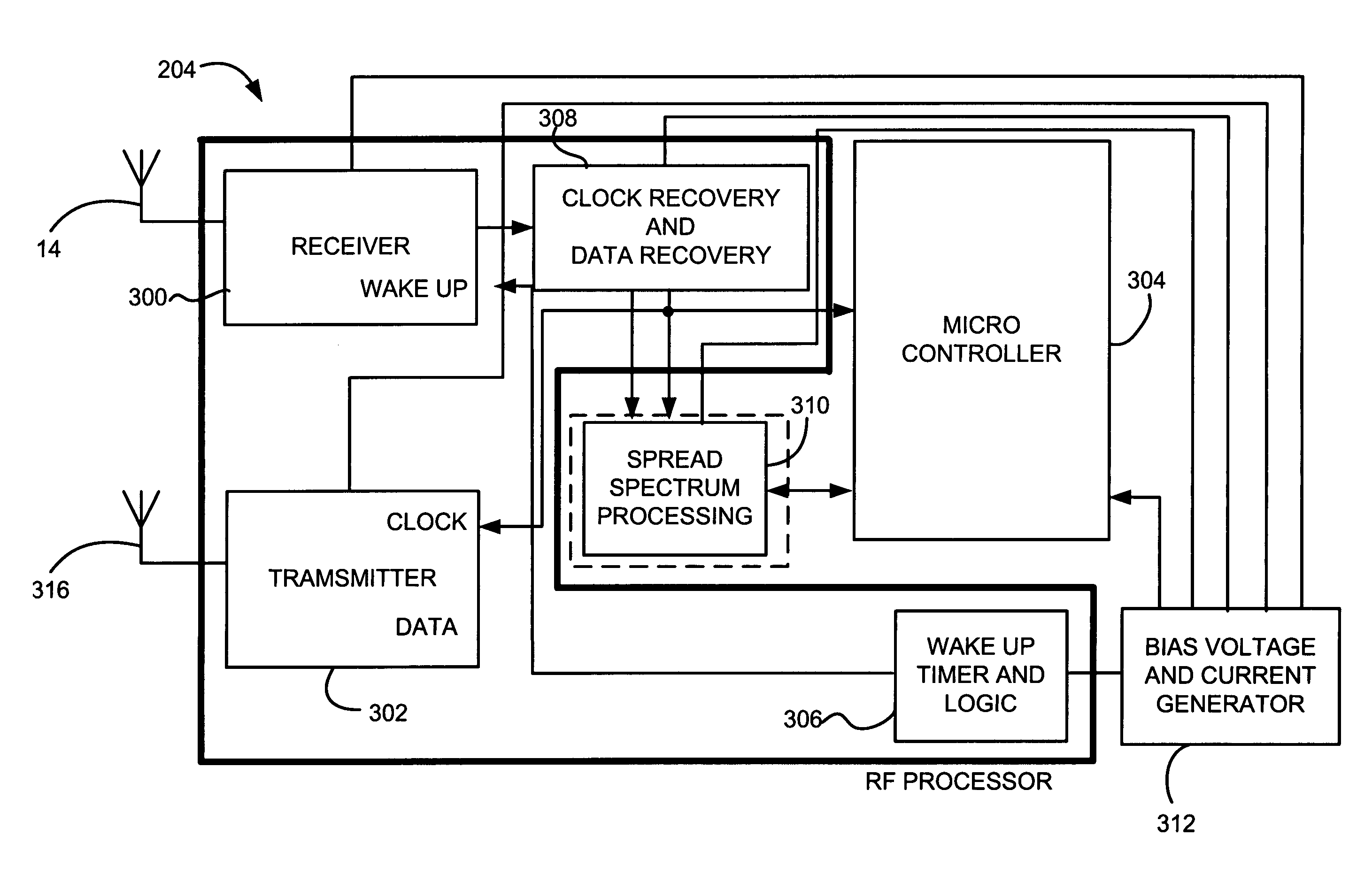
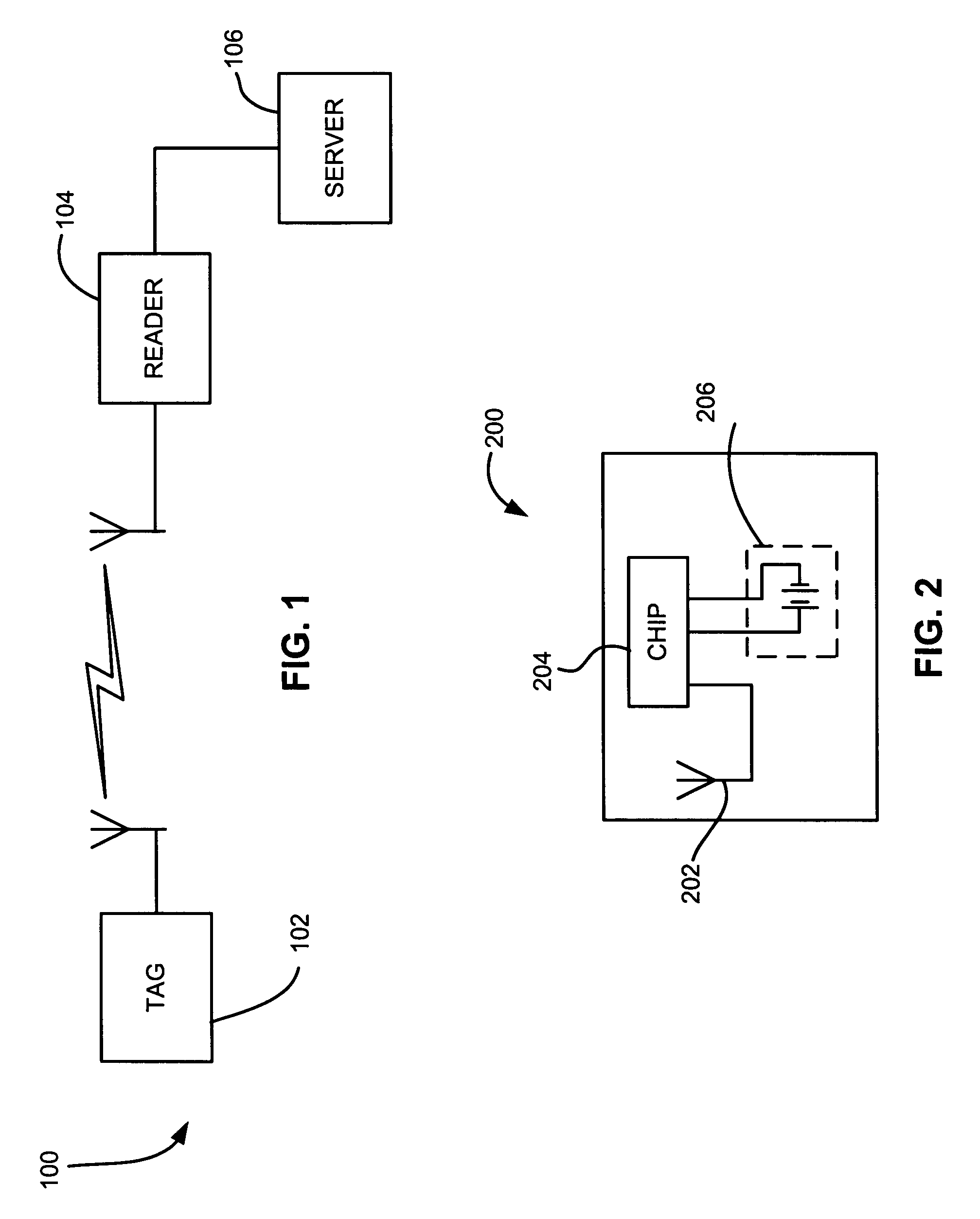
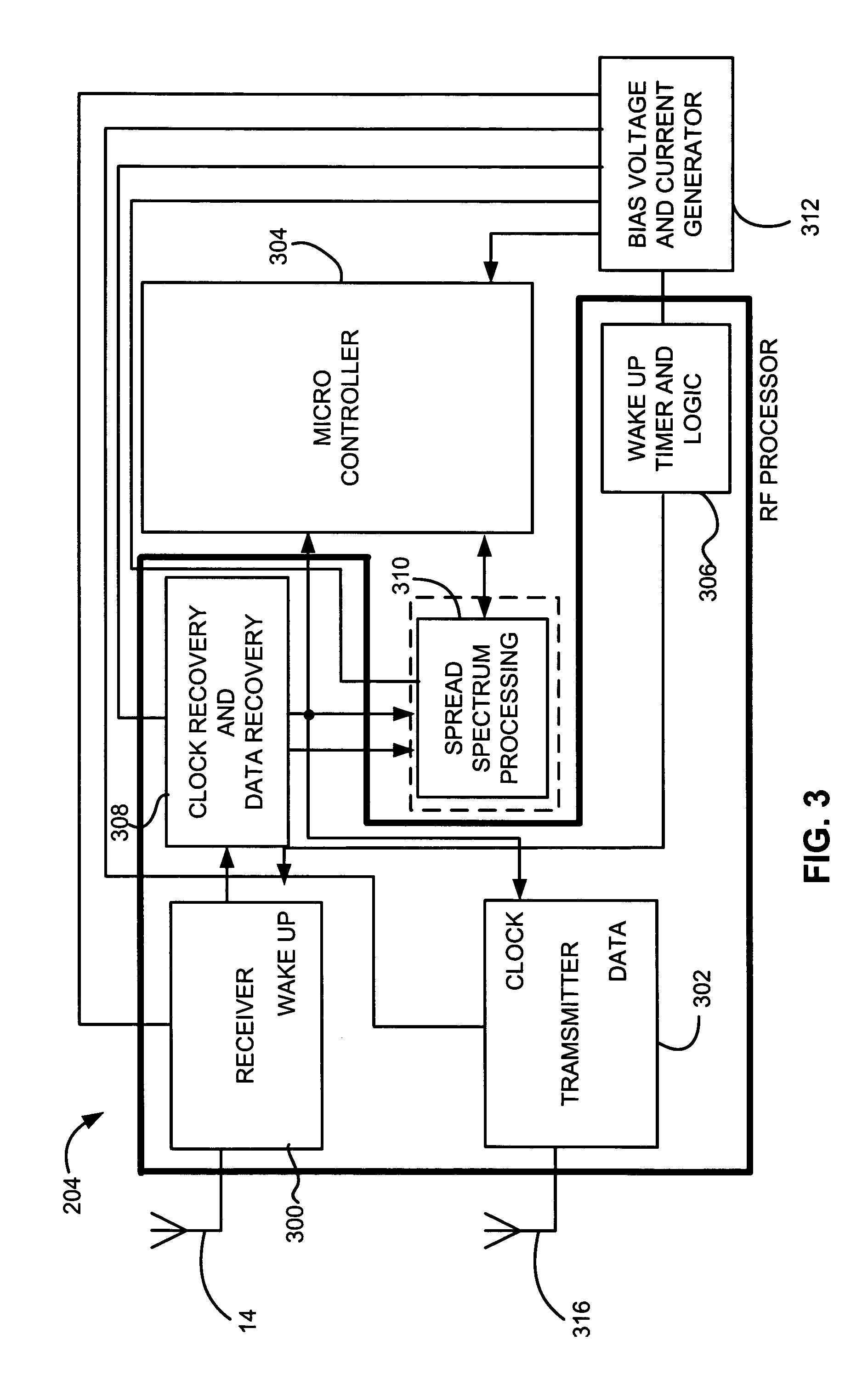
[0040] Many types of devices can take advantage of the embodiments disclosed herein, including but not limited to Radio Frequency Identification (RFID) systems and other wireless devices / systems; pacemakers; portable electronic devic...


PUM


Abstract

A timing circuit that can function as an accurate persistent node in an RFID tag includes a power capture circuit for capturing power from a power source, and a counter circuit that provides a count representing a progression of time. The count can then be compared to a reference value representing a time constant of the circuit.

Description

RELATED APPLICATIONS [0001] The present invention is related to U.S. patent application Ser. No. ______, entitled “BATTERY MONITOR” and filed concurrently herewith, and which is incorporated by reference.FIELD OF THE INVENTION [0002] The present invention relates to timing circuits, and more particularly, this invention relates to systems and methods for one shot timing circuits (persistent nodes) with long timing cycles. BACKGROUND OF THE INVENTION [0003] Radio Frequency Identification (RFID) technology employs a radio frequency (“RF”) wireless link and ultra-small embedded computer circuitry. RFID technology allows physical objects to be identified and tracked via these wireless “tags”. It functions like a bar code that communicates to the reader automatically without requiring manual line-of-sight scanning or singulation of the objects. RFID promises to radically transform the retail, pharmaceutical, military, and transportation industries. [0004] Several advantages of RFID techn...

Claims


Application Information

Patent Timeline
Patent Type & Authority Applications(United States)
IPC IPC(8): H04Q5/22
CPCG06K19/0723H03F3/45076G06M3/02G05F3/16
Inventor STEWART, ROGER GREEN
Owner ZEST LABS INC
Why Eureka
Try Eureka