Imaging apparatus and method for processing imaging results

a technology of imaging apparatus and image, applied in the field of imaging apparatus, can solve the problems of difficult detection of subjects if the background is moving, and achieve the effect of detection easily and reliably

Inactive Publication Date: 2006-11-09
SONY CORP
View PDF5 Cites 13 Cited by
  • Summary
  • Abstract
  • Description
  • Claims
  • Application Information

AI Technical Summary

Benefits of technology

[0012] According to an embodiment of the present invention, even if a background is moving due to p...

Problems solved by technology

In known methods for detecting subjects by using motion vectors, it is difficult to...

Method used


Image

  • Imaging apparatus and method for processing imaging results
  • Imaging apparatus and method for processing imaging results
  • Imaging apparatus and method for processing imaging results

Examples


first embodiment

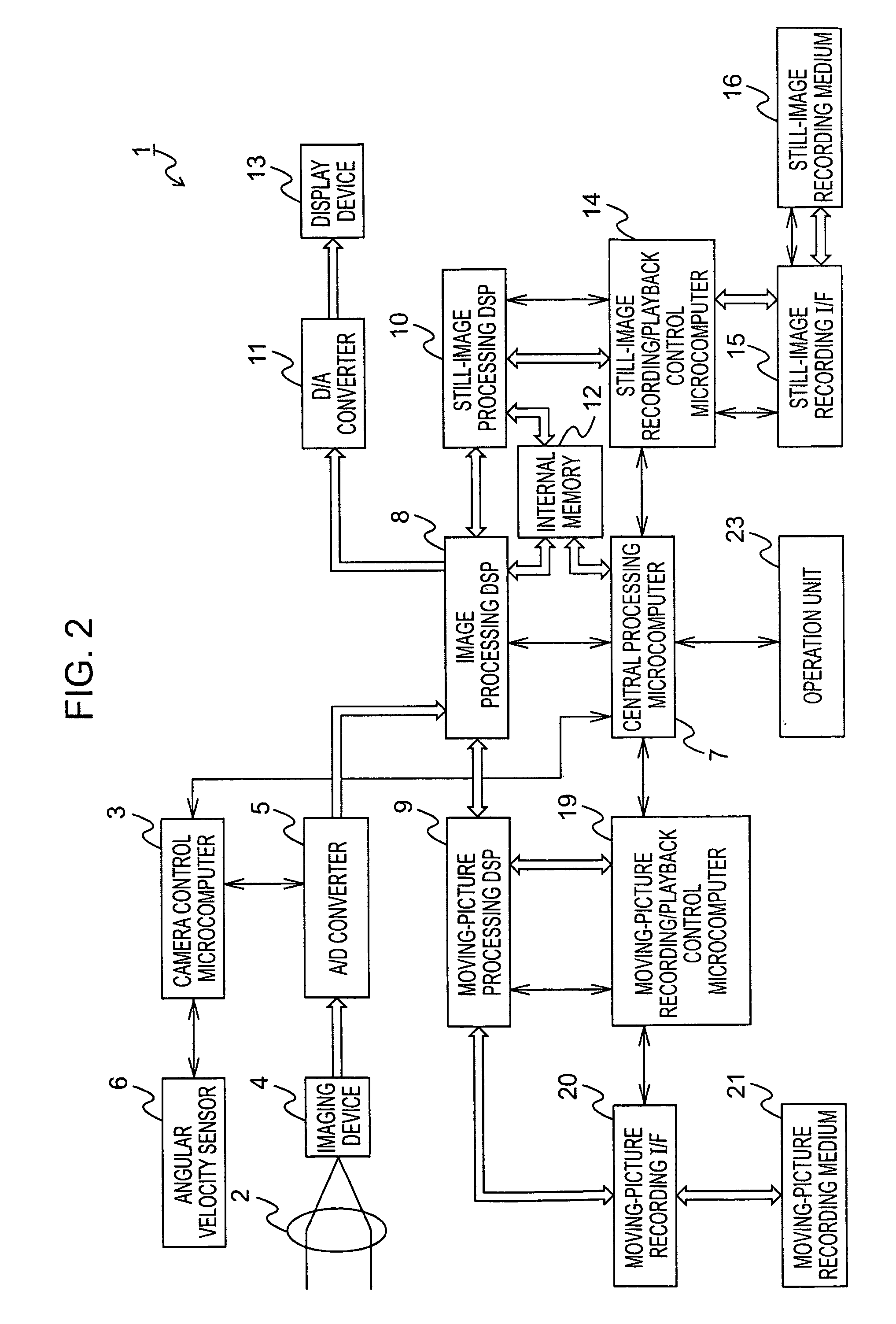
[0025]FIG. 2 is a block diagram illustrating an imaging apparatus 1 according to a first embodiment of the present invention. The imaging apparatus 1, which is a digital video camera, records imaging results of moving pictures and still images on a recording medium or plays back the imaging results recorded on the recording medium in response to an operation from a user.

[0026] In the imaging apparatus 1, a lens 2 condenses light to form an optical image on the imaging plane of an imaging device 4 by varying the magnifying power or the focus under the control of a camera control microcomputer 3.

[0027] The imaging device 4 includes a charge-coupled device (CCD) solid-state imaging element, a complementary metal oxide semiconductor (CMOS) solid-state imaging element, etc., and photoelectrically converts optical images formed on the imaging plane to output imaging results of moving pictures or still images. In the first embodiment, the lens 2 forms an optical system for forming optica...

second embodiment

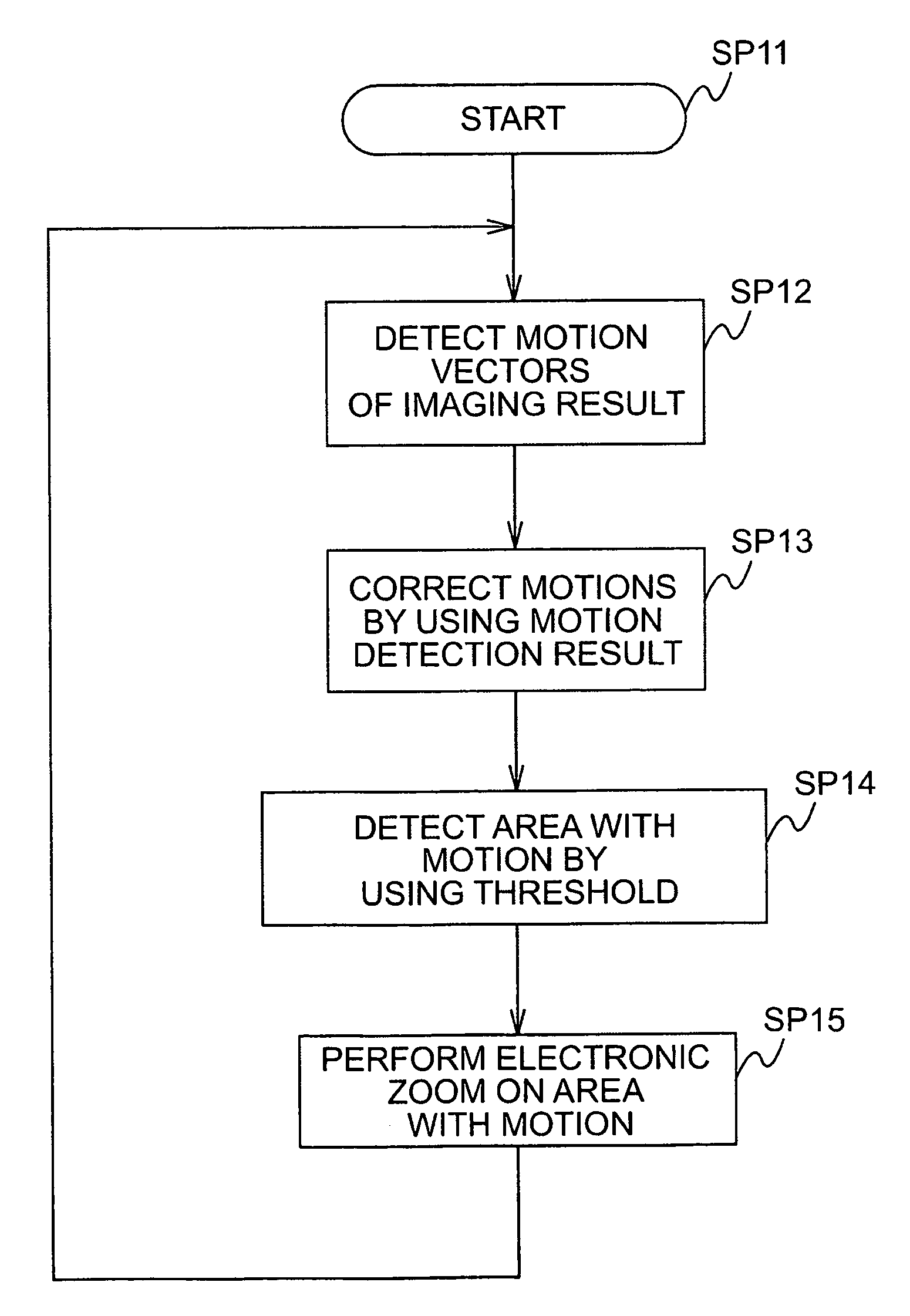
[0082] In a second embodiment, the generation of index images in the imaging apparatus 1 is performed when imaging results are recorded. Additionally, in response to an instruction from the user, an electronic zoom operation is performed while moving-picture imaging results are being recorded. The imaging apparatus 1 of the second embodiment is the same as that of the first embodiment, except that the index-image generating processing and the electronic zoom processing are performed on imaging results output from the A / D converter 5 and motion information output from the camera control microcomputer 3 instead of imaging results and motion information played back from the moving-picture recording medium 21.

[0083] According to the second embodiment, advantages similar to those obtained by the first embodiment can be achieved.

third embodiment

[0084] In a third embodiment, the optical system is controlled by using the relative motions of the individual parts of an imaging result with respect to a background, which are detected in the first or second embodiment. The imaging apparatus 1 in the third embodiment is the same as that of the first embodiment, except that the elements related to the controlling of the optical system are different from those in the first embodiment, and thus, an explanation is given by using the imaging apparatus 1 shown in FIG. 2.

[0085] In the third embodiment, in response to an instruction to photograph moving pictures from the user, the central processing microcomputer 7 starts processing indicated by the flowchart in FIG. 11. The central processing microcomputer 7 proceeds from step SP31 to SP32. In step SP32, the central processing microcomputer 7 detects an area containing a subject which is being photographed, as in the first embodiment, by using imaging results output from the A / D convert...


PUM


Abstract

An imaging apparatus for recording an imaging result on a recording medium includes an imaging device operable to obtain an imaging result; an optical system operable to form an optical image on an imaging plane of the imaging device; a first motion detector operable to detect a movement of the imaging apparatus and to output a detection result; and a recorder operable to record the imaging result, together with the detection result, on the recording medium.

Description

CROSS-REFERENCE TO RELATED APPLICATIONS [0001] The present application claims priority from Japanese Patent Application No. JP 2005-110461 filed on Apr. 7, 2005, the disclosure of which is hereby incorporated by reference herein. BACKGROUND OF THE INVENTION [0002] The present invention relates to imaging apparatuses, such as digital video cameras, and methods for processing imaging results. More particularly, the invention relates to an imaging apparatus and a method for processing imaging results, in which imaging results can be processed on the basis of information concerning the motion of the imaging apparatus obtained by a motion detector, such as an angular velocity sensor or an acceleration sensor, so that subjects can be detected by easily and reliably even if a background is moving due to panning or tilting, and as a result, various processing operations can be performed. [0003] In some known recording / playback devices, such as optical disc drives, representative images are ...

Claims


Application Information

Patent Timeline
IPC IPC(8): G03B41/00G03B17/00
CPCG03B17/24H04N5/232H04N5/23245H04N5/23248H04N5/23254H04N5/23258G06T2207/20201H04N5/23264H04N5/23296H04N5/85H04N9/7925H04N9/8205G06T5/003H04N5/23261H04N23/6815H04N23/682H04N23/6811H04N23/68H04N23/6812H04N23/667H04N23/632H04N23/69
Inventor TABUCHI, TATSUHITOHARADA, TAKESHISAITOU, YUJITSUSHIO, KENJIOKUMURA, ATSUSHIOGATA, TETSUJI
Owner SONY CORP
Why Eureka
Try Eureka