Rotational drive apparatus for screw pilings

a technology of rotating drive and screw pilings, which is applied in the direction of bulkheads/piles, drilling machines and methods, constructions, etc., can solve the problems of large apparatus, high cost, and inability to be utilized in the area, and achieves convenient transportation, sufficient torque, and economic production.

Active Publication Date: 2006-11-09
DESANTIS BROOKE ERIN
View PDF7 Cites 50 Cited by
  • Summary
  • Abstract
  • Description
  • Claims
  • Application Information

AI Technical Summary

Benefits of technology

[0008] Another feature of the present invention is to provide a rotational drive apparatus for screw pilings which is lightweight and easily transportable and which provides sufficient torque to drive the pilings within the earth.
[0009] Another feature of the present invention is to provide a drive apparatus for screw pilings which may be used in ecological areas to drive pilings into a swamp area while preserving the environment as the apparatus does not use toxic matter and is non-polluting.
[0010] Another feature of the present invention is that the rotational drive apparatus can be used in areas with limited headroom for the reason that the drive apparatus is not connected at the top of the pilings and can be adapted to shorter, interconnectable, piling sections.
[0011] Another feature of the present invention is to provide a rotational drive apparatus for screw pilings and wherein the apparatus can be used in harsh climatic conditions such as for driving pilings through snow covered earth.
[0012] Another feature of the present invention is to provide a rotational drive apparatus for screw pilings and which apparatus is economical to produce thereby reducing the cost of installation of such pilings and wherein the drive is automatically controlled by a user person and further wherein the drive is adapted to install screw pilings within a ground surface or remove them therefrom.

Problems solved by technology

A disadvantage of such system is that the apparatus is large, is expensive to use and its use is restricted to open space areas.
It cannot be utilized in areas where there is no access provided for this heavy machinery.
However, in hard ground surfaces this requires a lot of force by the user and accordingly the use of such screw pilings is restricted to loose soil.
Another disadvantage of known screw piling systems is that they require at least three people to operate and it is therefore labour intensive.
Another person is necessary to maintain the piling substantially vertically and a third person is required whereby to operate the motor as such pilings are very unstable as they begin to penetrate within the ground surface.
These systems are also hazardous to the operators.
The installation can also be time-consuming as well as labour intensive and therefore this method is very costly.
Known devices are also not ergonomically designed and are bulky and heavy, a further reason why they are labour intensive and difficult to use in remote hard-to-reach areas.

Method used


Image

  • Rotational drive apparatus for screw pilings
  • Rotational drive apparatus for screw pilings
  • Rotational drive apparatus for screw pilings

Examples


Embodiment Construction

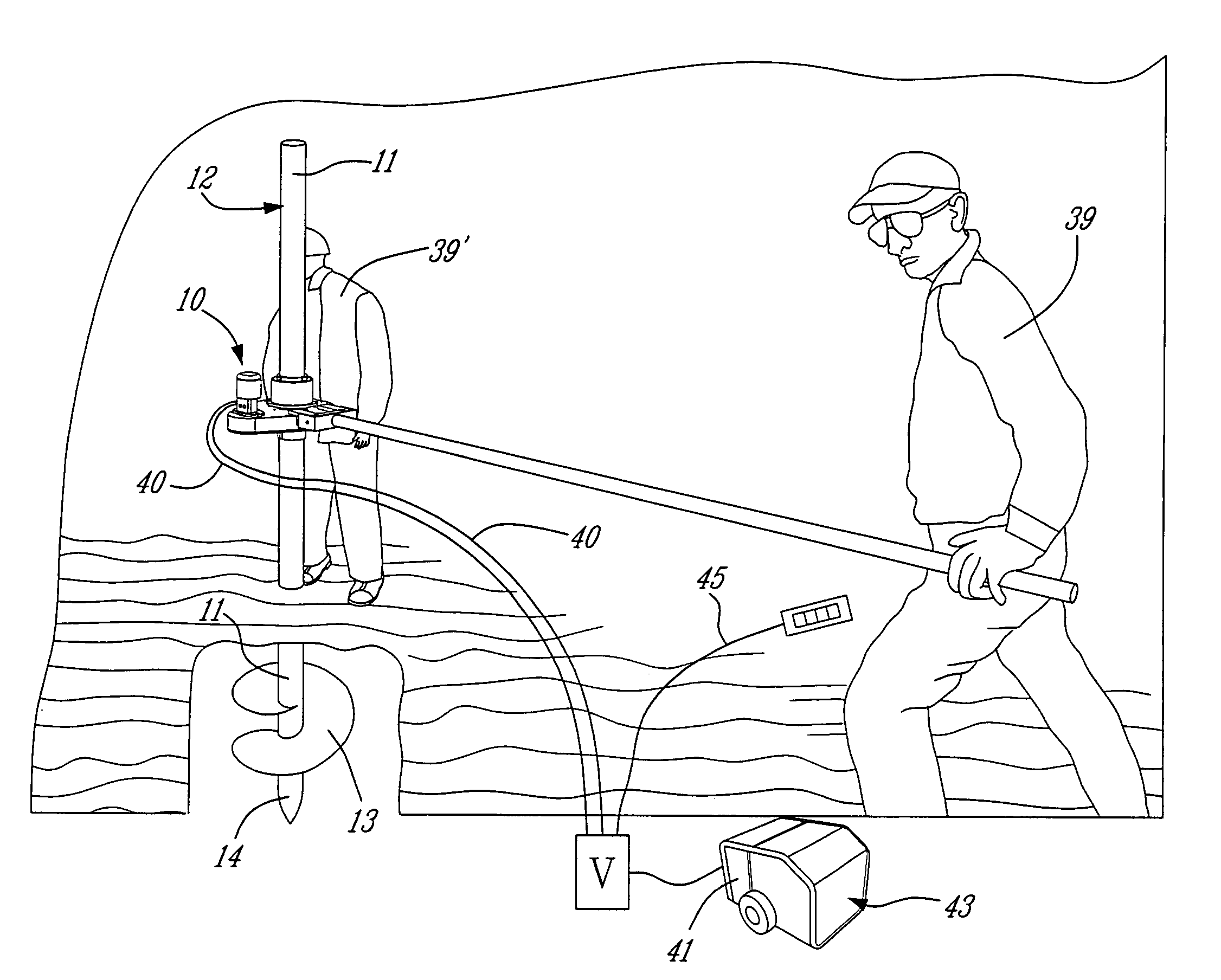
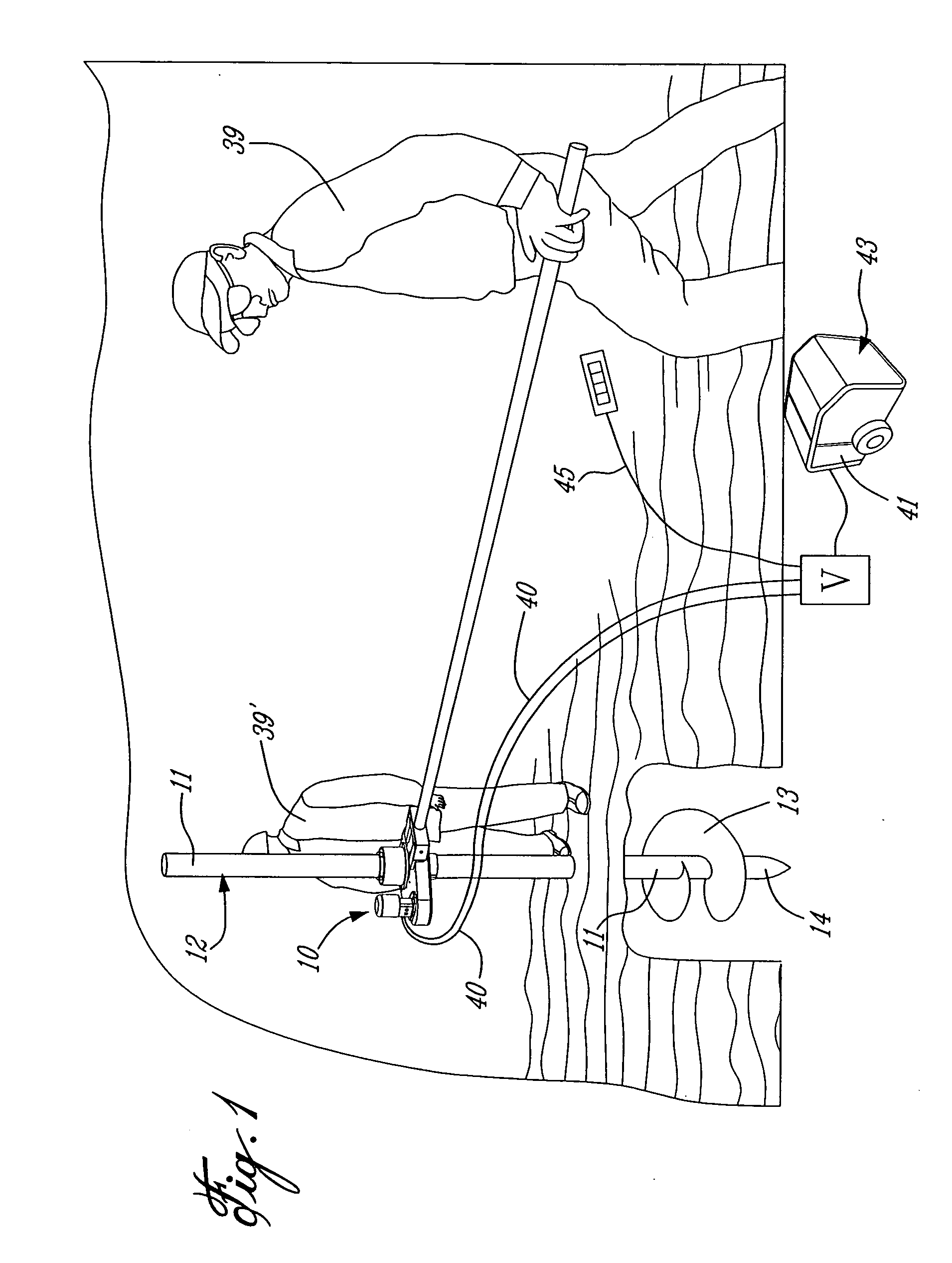
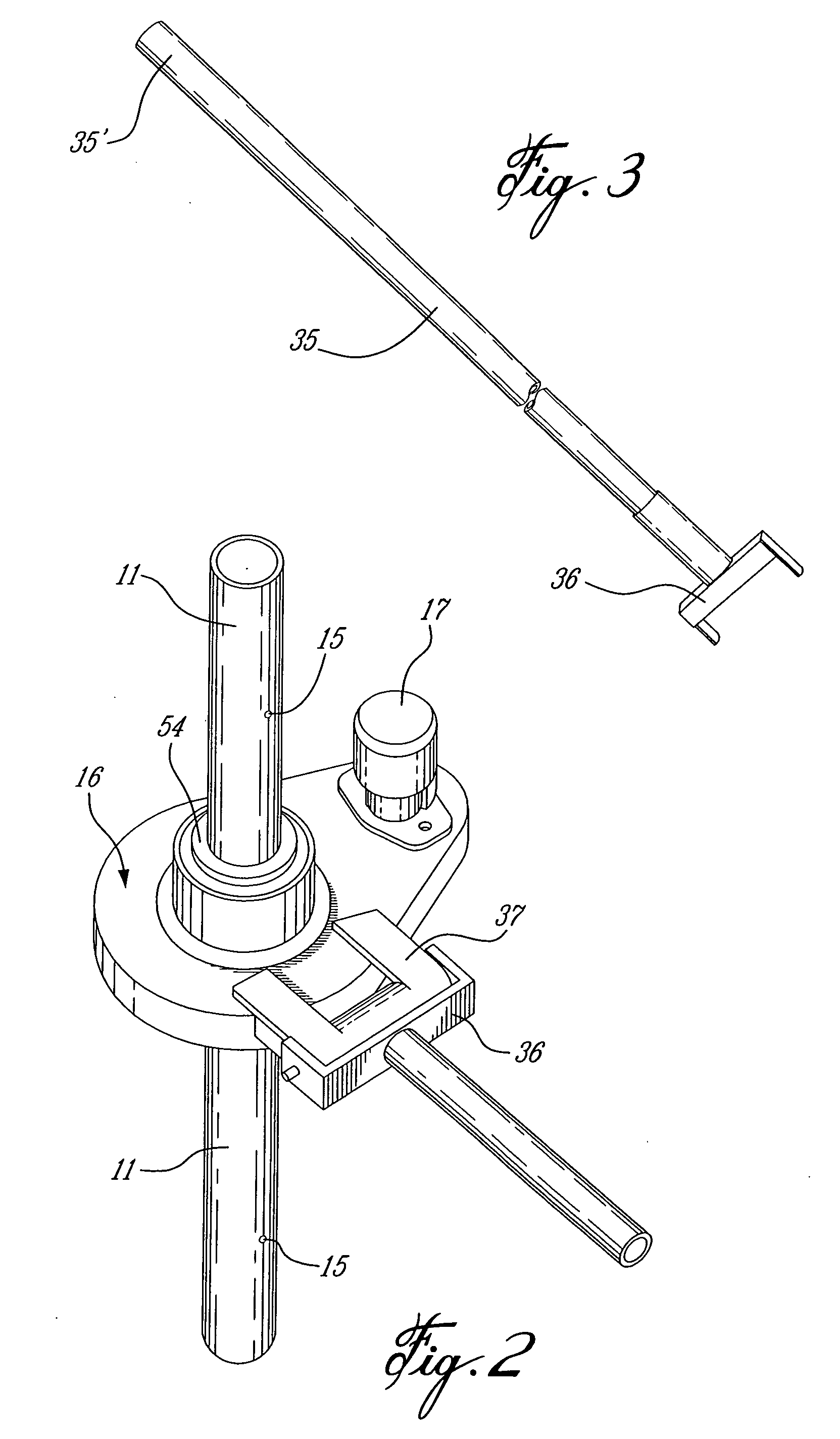
[0022] Referring now to the drawings there will be described the rotational drive apparatus of the present invention. As shown in FIG. 1, the rotational drive apparatus 10 is secured along a shaft 11 of a screw piling 12 which is provided with a drive helix 13 secured at a lower end 14 thereof. The shaft 11 is a hollow shaft as shown in FIG. 2 and is provided with a plurality of spaced-apart holes 15 therealong. The drive apparatus comprises a housing 16 in which is located a drive connection and a coupling to impart rotation to the shaft 11 of the screw piling 12. A drive motor 17 is the power source for the drive.

[0023] With reference to FIGS. 4, 5 and 6, there is illustrated the construction of the rotational drive component and the shaft coupling. A cylindrical pipe coupling 20 is herein illustrated secured vertically with respect to the horizontal plane 21 of the housing 16. The pipe coupling 20 is secured to the bottom end 22 of a rotational guide sleeve 23 which is dimension...


PUM


Abstract

A rotational drive apparatus for screw pilings is described. The apparatus comprises a housing having a cylindrical pipe coupling adapted to receive a shaft of a screw piling therethrough. A detachable connecting element secures the coupling to the shaft at different positions along the shaft. A rotational drive is provided within the housing for imparting rotation to the coupling. An elongated rod is secured to the housing and is held by a user person whereby to immobilize the housing wherein to permit the rotational drive to transmit a drive force to the coupling to rotate the shaft of a screw piling.

Description

TECHNICAL FIELD [0001] The present invention relates to a rotational drive apparatus for screw pilings and particularly to an apparatus which is transportable and which imparts a rotational drive to a coupling secured to the shaft of a piling. The apparatus is immobilized by a user person by the use of an elongated rod secured to the housing of the apparatus. BACKGROUND ART [0002] Screw pilings are known which comprise a shaft having a helix secured at a lower end thereof whereby to drive the piling into the ground when the shaft thereof is rotated in a clockwise direction. To impart a rotational drive to such shafts, heavy machinery is used whereby to attach a rotational drive to the top end of the shaft of the piling. An example of this system is described in U.S. Pat. No. 5,066,168. A disadvantage of such system is that the apparatus is large, is expensive to use and its use is restricted to open space areas. It cannot be utilized in areas where there is no access provided for th...

Claims


Application Information

Patent Timeline
Patent Type & Authority Applications(United States)
IPC IPC(8): E02D7/00
CPCE02D7/22
Inventor DESMEULES, NORBERT
Owner DESANTIS BROOKE ERIN
Why Eureka
Try Eureka