Sterilizing apparatus

a technology of sterilizing apparatus and sterilizing chamber, which is applied in the field of sterilization, can solve the problems of insufficient sterilization of articles, inability to obtain optimal saturated steam environment, and still damp articles

Active Publication Date: 2006-11-09
MIDMARK
View PDF15 Cites 48 Cited by
  • Summary
  • Abstract
  • Description
  • Claims
  • Application Information

AI Technical Summary

Benefits of technology

The present invention is a sterilizer that uses pressure to control the heating of a chamber where articles are placed for sterilization. By monitoring the pressure, the sterilizer can accurately maintain the chamber temperature close to the set point, ensuring proper sterilization of the articles. This technology provides a more precise and reliable method of sterilizing articles.

Problems solved by technology

The technical problem addressed in this patent text is the need for a sterilizer that can overcome shortcomings and drawbacks that have occurred during sterilization cycles, including inadequate sterilization, excessive drying time, and noise caused by opening the sterilizer door. The patent aims to provide a solution that can improve the sterilization process and provide a better user experience.

Method used


Image

  • Sterilizing apparatus
  • Sterilizing apparatus
  • Sterilizing apparatus

Examples


Embodiment Construction

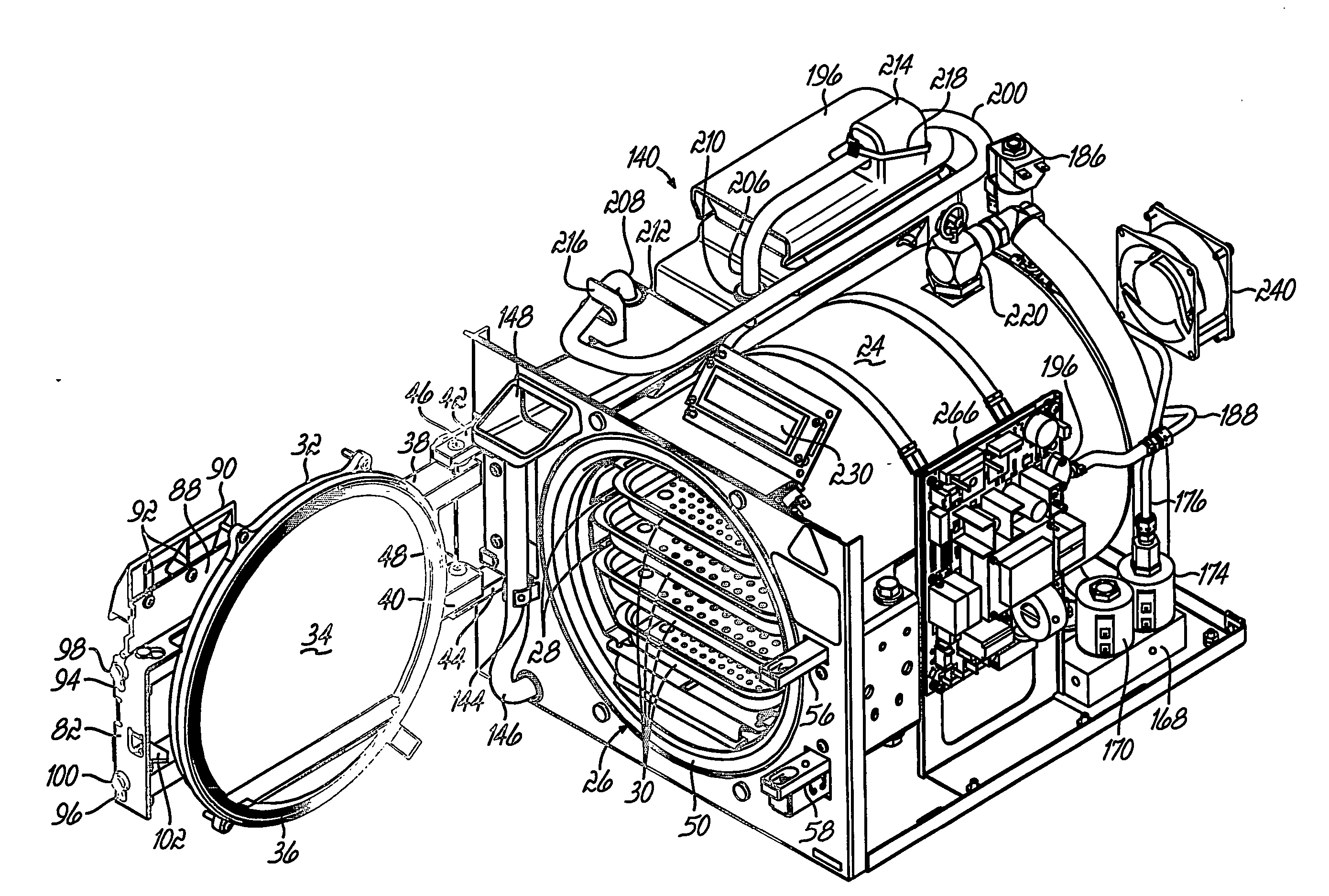
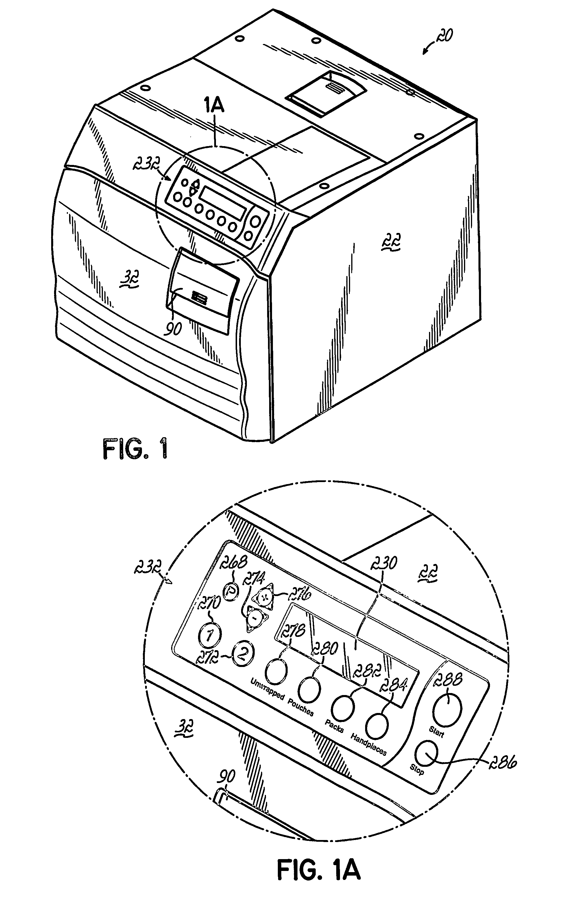
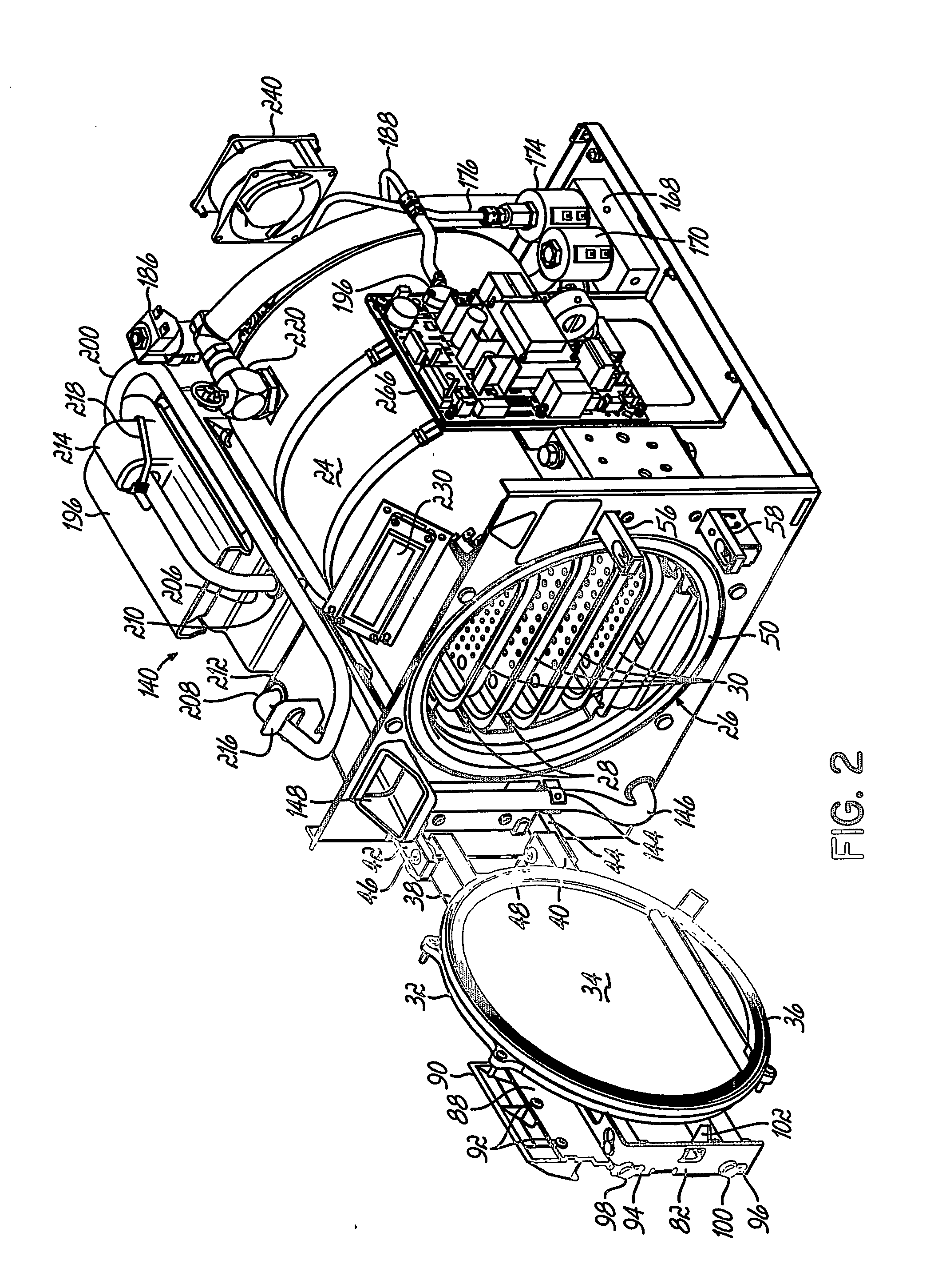
[0038] Referring to Figures, and to FIGS. 1-4 in particular, a sterilizer 20 in accordance with the principles of the present invention includes an outer housing 22 within which a sterilizer chamber 24 is enclosed. The sterilizer chamber 24 includes an opening 26 (FIG. 2) at a front portion of the sterilizer 20 which is configured to receive articles (not shown) to be placed inside the sterilizer chamber 24. As may be seen in FIG. 2, the sterilizer chamber 24 is provided with support rails 28 for supporting article trays 30 within the chamber 24.

[0039] A door 32 defines a front portion of the sterilizer housing 22 and includes a chamber sealing plate 34 and an annular chamber seal 36 supported by the sealing plate 34. The sealing plate 22 is supported by upper and lower horizontal support bars 38, 40 which are mounted to respective horizontal supports 42, 44 by pivot pins 46, 48. Thus, the door 32 may be pivoted about a vertical axis toward and away from the chamber 24 whereby the ...


PUM


Abstract

A sterilizer (20) is provided having a steam filled sterilizer chamber (24) for sterilizer articles placed within the chamber (24). An electronic air valve (186) is provided to control the venting rate of the steam is vented back to a water reservoir (140) after the articles have been sterilized. The electronic air valve (186) also vents the chamber (24) in a controlled manner during the heat up portion of the sterilization cycle to obtain an optimum saturated steam environment with the chamber (24) for the sterilizing process. The sterilizer (20) has pre-programmed and programmable sterilization cycles. And the drying times of each of these cycles is programmable by a user. The programmable sterilization cycles also provide a programmable vent rate which may be selected by the user to minimize damage to the sterilized articles. A steam condensing coil (200) is associated with the water reservoir (140) to minimize pressure build up within the water reservoir (140). The sterilizer (20) uses sensed pressure within the sterilizer chamber (24) to control heating of the chamber (24) to a predetermined sterilization temperature set point during a sterilization cycle. A motor (114) controls a door lock mechanism to open the door (32) of the sterilizer (20) following the sterilizing portion of the sterilization cycle.

Description


Claims


Application Information

Patent Timeline
Owner MIDMARK
Why Eureka
Try Eureka