Generator arrangement for a wind power plant

Inactive Publication Date: 2010-10-21
SCHULER PRESSEN GMBH & CO KG
View PDF4 Cites 47 Cited by
  • Summary
  • Abstract
  • Description
  • Claims
  • Application Information

AI Technical Summary

Benefits of technology

[0007]With the generator arrangement according to the invention at least one main bearing is arranged between the generator and the hub wherein the rotor of the generator

Problems solved by technology

The arrangement of the main bearing within the directly driven generator can result in problems regarding the establishment of a sufficiently rigid support structure.
At the same time, however, the weight of the generator is an important expense factor.
It results not only in

Method used


Image

  • Generator arrangement for a wind power plant
  • Generator arrangement for a wind power plant
  • Generator arrangement for a wind power plant

Examples


Example

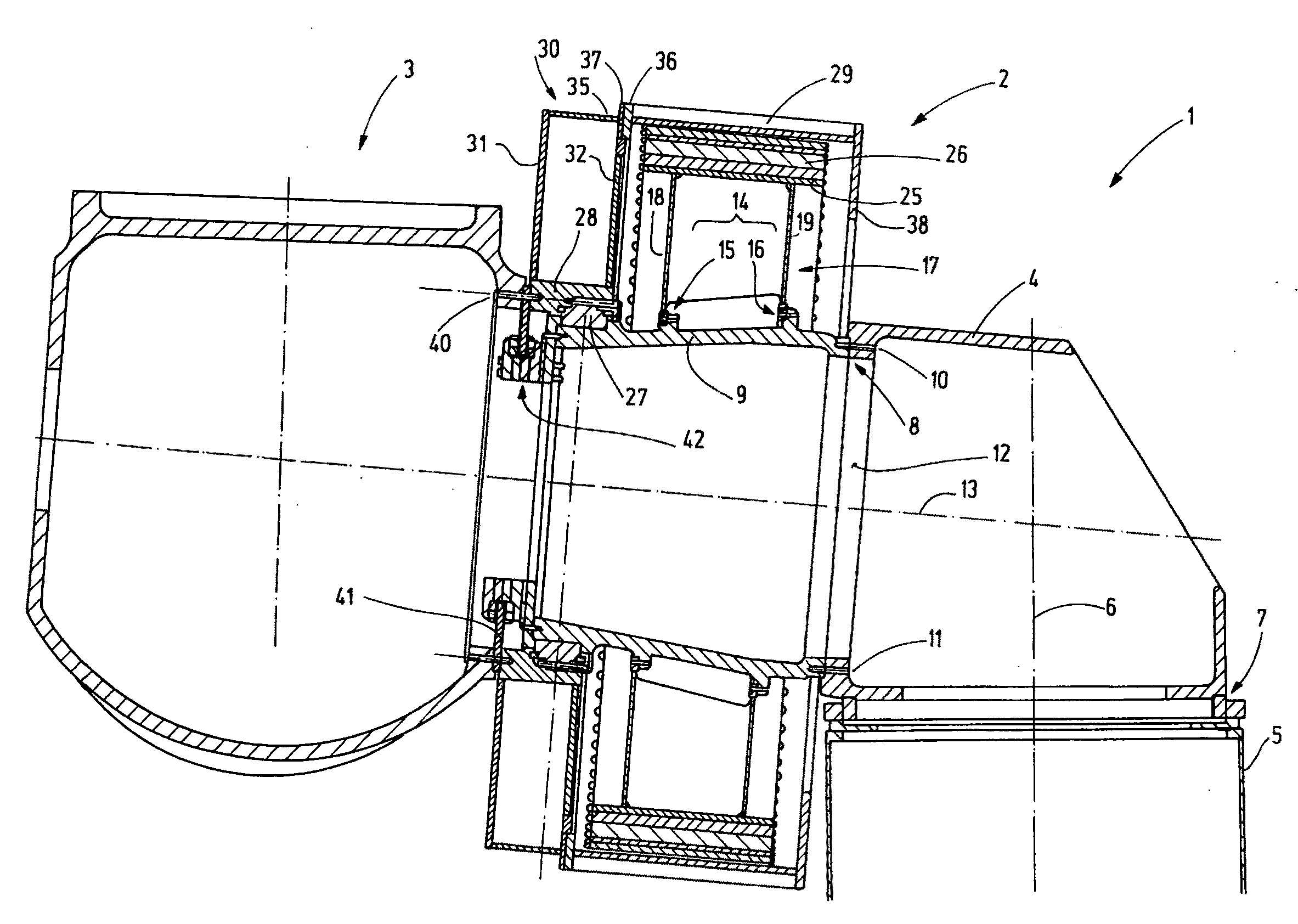
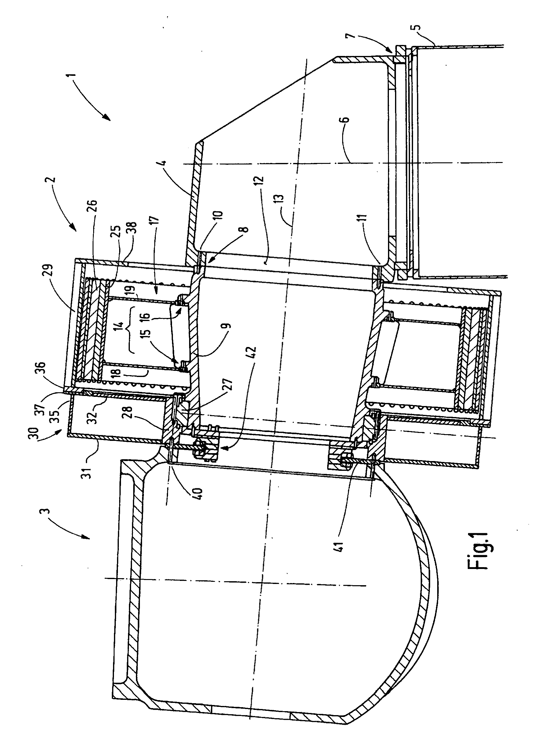
[0023]FIG. 1 shows a tower head 1 with a generator 2 and a hub 3 of a wind power plant. The tower head includes a machine carrier 4 which is supported at the upper end 5 of the tower so as to be rotatable about a vertical axis 6. To this end the tower is provided with a tower bearing 7.

[0024]In the shown embodiment the machine carrier 4 is relatively compact. It extends sidewardly only slightly beyond the upper end 5 of the tower. At one side, in FIG. 1 at the left, the machine carrier 4 is provided with a support structure 8 for supporting a support tube 9 forming a stationary axle. The support tube 9 is provided at its side adjacent the machine carrier 4 with a precisely machined annular surface which forms a sealing surface to which a corresponding annular surface formed on the machine carrier 4 is assigned. The annular surface of the machine carrier 4 may be surrounded by an annular stepped area so that the support tube is seated on the machine carrier 4 in a centered manner. As...


PUM


Abstract

In the generator arrangement according to the invention at least one main bearing is arranged between the generator and the hub wherein the rotor of the generator is supported only on the front end of a rigid carrier in the form of a support disc (30). The support disc is a hollow chamber structure of low weight and high rigidity.

Description

CROSS-REFERENCE TO RELATED APPLICATION[0001]This application claims the priority benefits of German Application No. 10 2009 017 865.1 filed Apr. 17, 2009.BACKGROUND OF THE INVENTION[0002]The invention resides in a generator arrangement for wind energy utilization. Plants for wind energy utilization generally comprise a vertical extending tower on the top of which a gondola is supported so as to be rotatable about a vertical axis. The gondola supports a generator which is usually driven by a three-blade rotor. One of the employed drive concepts is a direct drive wherein the hub of the rotor carrying the blades is connected to the rotor of a generator directly without an intermediate transmission.[0003]Such a concept is shown in DE 44 02 184 C2, wherein the generator is in the form of an external rotor. The stator and the rotor of the generator are joined by a resilient bearing structure which is arranged within the generator and which supports the rotational movement of the rotor as ...

Claims


Application Information

Patent Timeline
IPC IPC(8): F03D1/00
CPCF03D11/0008H02K1/187Y02E10/72H02K1/30H02K7/183H02K1/2786H02K7/1838F03D80/70H02K1/2791
Inventor LAUKE, ANDREAS
Owner SCHULER PRESSEN GMBH & CO KG
Why Eureka
Try Eureka