

Sprocket particularly for conveyor belts or chains
a technology of conveyor belts and sprockets, which is applied in the direction of conveyors, gearing elements, portable lifting, etc., can solve the problems of hub parts having substantially cylindrical shapes, increasing the production costs of these modular sprockets, and hub parts breaking or affecting the operation of the hub, so as to reduce manufacturing and assembly costs
- Summary
- Abstract
- Description
- Claims
- Application Information
AI Technical Summary
Benefits of technology
Problems solved by technology
Method used
Image

Examples
Embodiment Construction
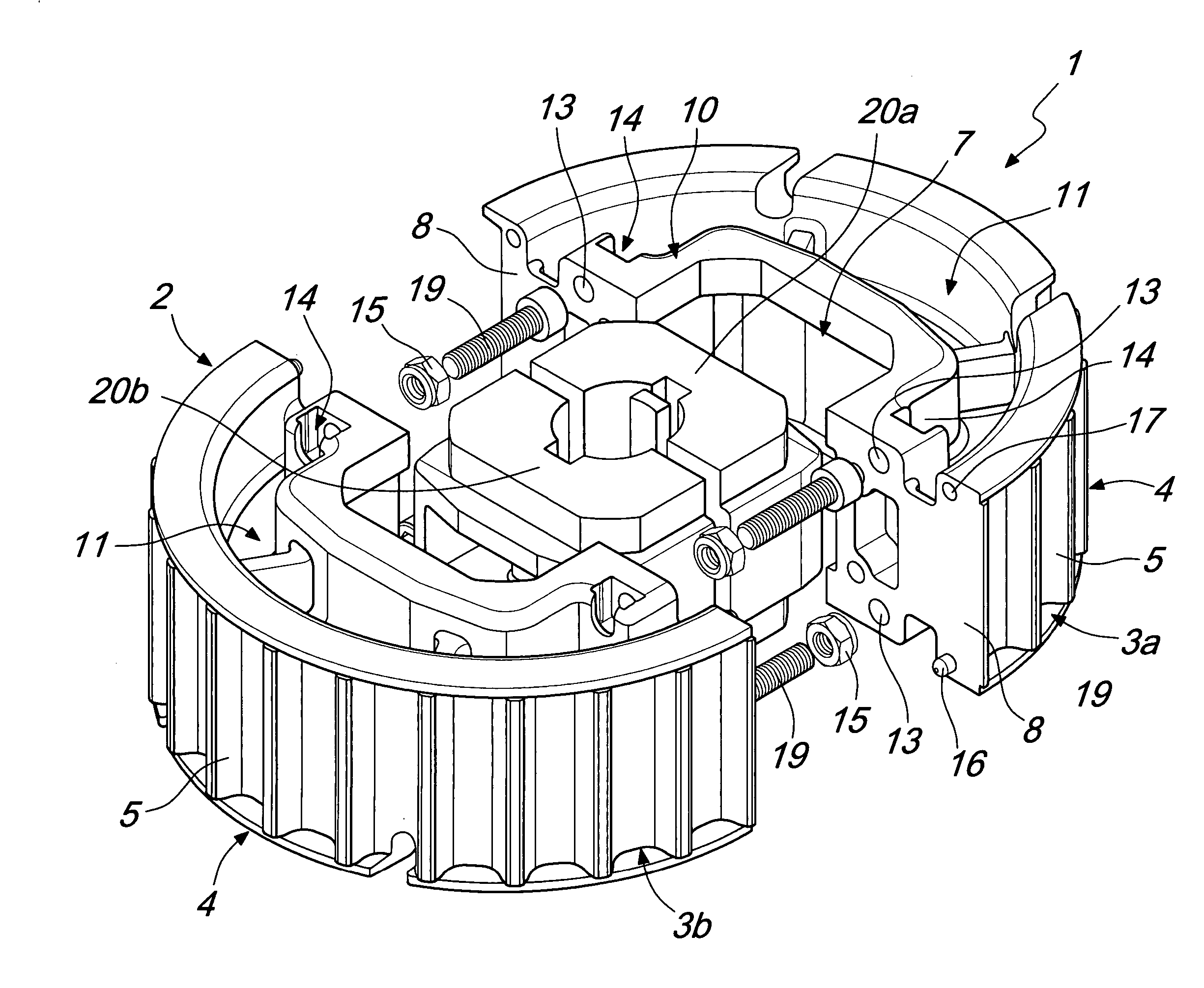
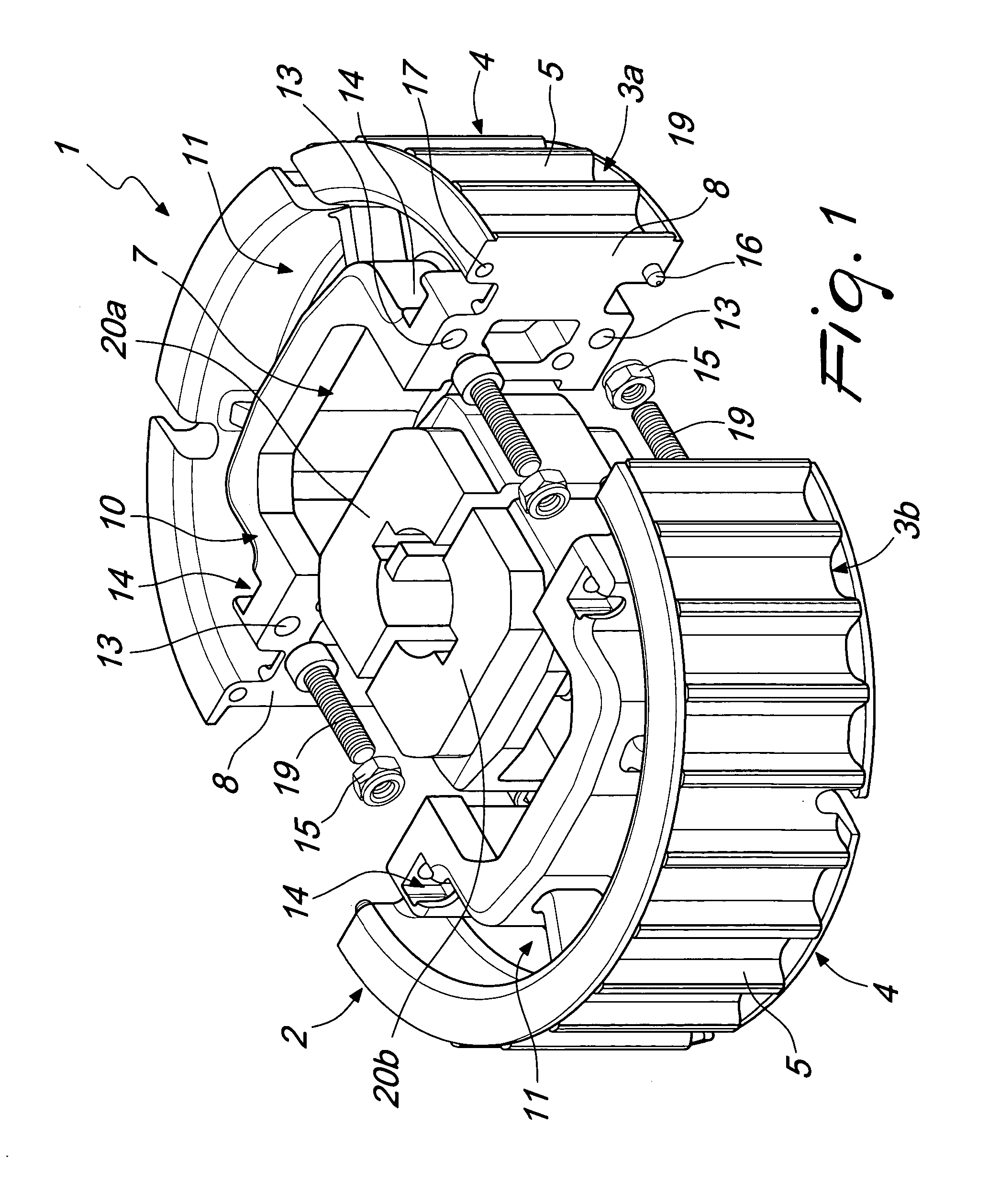
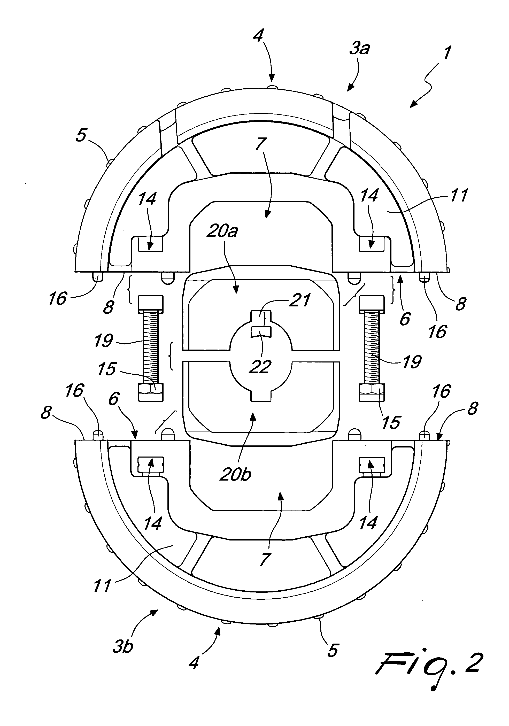
[0035] With reference to the figures, the reference numeral 1 designates a sprocket, particularly for conveyor belts or chains.
[0036] The sprocket 1 comprises a spur gear 2, which is constituted by two mirror-symmetrical spur halves, designated respectively by the reference numerals 3a and 3b, which are substantially semicircular and from the curved outer surface 4 of which a series of teeth 5 protrude radially, said teeth being engageable for example with a conveyor belt or chain, not shown in the accompanying figures. Each one of the two spur halves 3a and 3b has, at the internal surface 6, a polygonal central seat 7 to which two substantially flat end faces 8 are contiguous, said end faces facing each other during use.
[0037] Once the two spur halves 3a and 3b have been arranged mutually adjacent at the end faces 8, the central seats 7 form an opening 9.
[0038] A recess 11 is formed on each one of the two lateral faces 10 of each one of the spur halves 3a and 3b and surrounds th...
PUM
 Abstract
Description
Claims
Application Information